
Section 4
Chemical Recovery
4.1 INTRODUCTION
Various technologies are used by plating shops to separate plating chemicals from rinse waters and air emissions or to concentrate them, thereby making them available for reuse/recycle. The most common technologies are:
- Atmospheric Evaporation
- Vacuum Evaporation
- Ion Exchange
- Electrowinning
- Electrodialysis
- Reverse Osmosis
- Meshpad Mist Eliminator
Although many of the recovery technology applications identified by the respondents have been successful, there are also many unsuccessful applications. The success/failure rate reported by respondents to the Users Survey varied by technology and application. Exhibit 4-1 presents a summary of the technologies and applications identified during the Users Survey and it shows the average success rating given by the respondents. Technology success was measured by respondents on a scale of 1 to 5, with 1 being the least successful and 5 being the most successful.
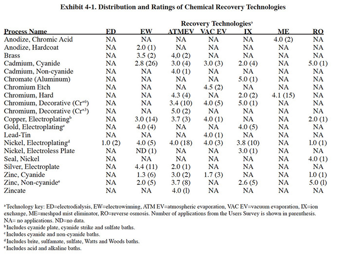
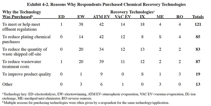
When evaluating success and failure ratings of the Users Survey, one must consider the reasons why the respondents purchased the recovery technologies. A summary of these data is presented in Exhibit 4-2. In the survey form, the respondents were given a choice of five specific reasons why they may have purchased the technology, plus an opportunity to list "other" reasons. The question was worded and formatted in a way that multiple responses were possible. The results are somewhat surprising in that reducing chemical purchases (i.e., recovering the plating chemicals), which is the primary function of recovery technologies, was not the most frequently given response. Rather, meeting or helping to meet effluent regulations was cited much more frequently. Reducing plating chemical purchases, reducing the quantity of waste shipped off-site and reducing wastewater treatment costs were cited approximately the same number of times as reasons for purchasing the recovery technologies.
The remainder of this section presents the results of the Users Survey, Vendors Survey and literature search with regard to the chemical recovery technologies employed by the survey respondents. The Users Survey requested platers to provide detailed technical, performance and operating cost data for chemical recovery technologies. The vendors were requested to provide technology descriptions, operating data and capital cost data. As a result of obtaining data from these two sources, plus the information from the extensive literature review, this section contains a substantial quantity of information for the following chemical recovery technologies: electrodialysis, electrowinning, atmospheric evaporators, vacuum evaporators, ion exchange, reverse osmosis and mesh pad mist eliminators. A separate subsection of the report is devoted to each of these technologies. Within each subsection, the following are provided: technology overview; development and commercialization; applications and restrictions (with diagrams showing different potential configurations); technology/equipment description; capital costs; operating costs; performance experience; and residuals generation. The capital cost curves contained in Section 4 are based on data collected from the technology vendors and the operating cost curves are based mainly on data from platers. Both the capital and operating cost information are expressed in 1993 dollars. A labor cost of $25 per hour (includes overhead) and an electricity cost of $0.10/kWh have been used, where applicable, in calculating operating costs.
4.2 ATMOSPHERIC EVAPORATORS
4.2.1 Overview
Atmospheric evaporators are the most widely used method of chemical recovery in the plating industry. Of the 318
plating shops responding to the Users Survey, 71 (or 22.3%) have employed atmospheric evaporators for chemical
recovery. Some shops have purchased or built two or more units for different recovery applications, resulting in a
total number of 91 units used by survey respondents. The literature cites an extreme case, where a Virginia shop
employs 14 atmospheric evaporators and has achieved zero discharge of wastewater effluent (ref. 33). Most of the
atmospheric evaporators used by survey respondents were commercial units although approximately 5% were built
in-house. By comparison, 26% of the electrowinning units were built in-house. The low percentage of home-made
atmospheric evaporation units is most likely due to the low capital cost and successful track record of the
commercial units.
Atmospheric evaporators are also used by some shops to concentrate liquid plating wastes prior to hauling them
off-site for treatment/disposal, thereby reducing transportation costs and in some cases treatment/disposal costs. A
total of 3 shops responding to the survey used atmospheric evaporators for this purpose.
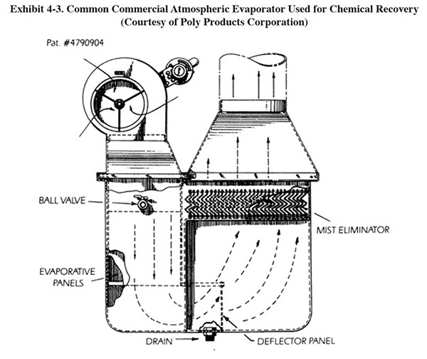
An atmospheric evaporator is a device that evaporates water to the atmosphere. The commercial atmospheric evaporator used for recovery in the plating shop consists of a pump to move the solution, a blower to move the air, a heat source, an evaporation chamber in which the solution and air can be mixed, and a mist eliminator to remove any entrained liquid from the exit air stream (see Exhibit 4-3). The evaporation chamber is usually filled with packing material or finned panels to increase the air to water interface. In operation, the temperature of the solution being evaporated is elevated and the heated solution is introduced into the evaporation compartment. Air from the plating room is then blown through the compartment where it accepts the water vapor, and is then vented out of the chamber.
Commercial units are advertised to have evaporation rates of 10 to 90 gph, depending on the size of the unit and operating conditions (e.g. solution temperature). Often actual evaporation rates are considerably less because the atmospheric conditions within most plating shops do not match the ideal conditions under which the manufacturers rate their systems. To meet higher evaporative requirements, it is feasible to utilize multiple atmospheric evaporators in series. However, the use of atmospheric evaporators is generally limited by energy costs to applications where the required evaporation rate is 50 gph or less. Beyond this point, vacuum evaporators (Section 4.3) are more cost effective, considering both capital and operating costs.
The key attributes of atmospheric evaporators include: (1) low capital cost; (2) simple operation and low maintenance; (3) very high recovery rates can be achieved (usually 90% to nearly 100%); (4) no additional reagents are needed; and (5) no sludges or only small quantities of sludges are generated (when used in recovery application). The major negative aspects of this technology are:(1) high energy requirement (i.e., requires constant solution heating and during the winter months there is a heat loss due to venting the exhaust to the outside); (2) the air that is vented by these devices must be discharged to the outside (due to contaminants present and its high humidity) and may be a regulated source of air pollution; (3) because moisture is exhausted to the atmosphere it cannot be reused as rinse water as with vacuum evaporators1; (4) evaporators return contaminants to the bath and may reduce bath life; and (5) spray/fog rinsing over the bath or fume suppressants (floating chemical type or plastic balls) are not compatible with atmospheric evaporators since they reduce the head room in the plating tank and limit the return of rinse water/dragout.
Most commercial atmospheric evaporator units have the same principals of operation. To achieve chemical recovery, solution from a heated plating tank is fed to and concentrated by the evaporator and returned to the plating tank. This approach reduces the volume of solution in the plating tank, thereby "making room" for the recovery rinse water/dragout to be added to the plating bath. Often two or more recovery rinse stations are used to minimize the overall rinse water requirements of the process and increase the recovery rate of plating chemicals. Less frequently, atmospheric evaporation is applied to ambient or low temperature baths. In this case, the recovery rinse water may be fed to the evaporator from a heated transfer tank, which increases the overall evaporative capacity of the system. The latter application is often restricted by the maximum temperature that can be applied to the solution, since heat sensitive components of the bath could be destroyed.
Although some commercial atmospheric evaporators have their own heat source, nearly all units employed for plating chemical recovery in use today use the heat in the plating tank (and/or heated transfer tank) as the energy source for evaporation. Any solution above room temperature that is pumped to the evaporator will be returned at a lower temperature. The temperature difference is primarily due to the heat that goes into evaporation, which is (ref. 358):
- 540 calories/g of water evaporated, or
- 2,137 Btu/l (8,090 Btu/gal), or
- 626 watts/l (2,371 watts/gal), or
- 0.02137 "gas company" therms/l (0.08090 therms/gal), or
- 0.0637 boiler hp/gal
The heat taken from the plating bath must be replaced by the tank heating system (e.g., immersion heaters or steam system) in order to maintain the operating temperature of the bath. During winter months, when a plating shop is heated, the room's ambient air that is exhausted by the evaporator (typically 300 to 3,000 cfm) must be replaced. These two elements make up the bulk of the non-labor operating costs for atmospheric evaporation.
The humidity and temperature of a plating shop will significantly affect the evaporative capacity of an atmospheric evaporator, especially for low to moderate solution temperature applications. If the air in the plating shop is very humid (e.g., 90% relative humidity) before entering the evaporation chamber, it will hold a limited amount of additional water and the evaporation rate will be affected. From thermodynamic tables, it is known that warmer air holds more moisture than cooler air. For example, one pound of air will hold 0.015 pounds of water at 70°F. By comparison, that same pound of air will hold 0.220 pounds of water at 120°F. In all cases, the air entering the evaporation chamber is heated to a maximum temperature equal to a point less than the solution temperature (the closeness of the air and solution temperatures will depend on the evaporator design and resultant heat transfer efficiency). With high temperature solutions, the air temperature will reach 100°F or more. At this temperature level, the original moisture content of the air is relatively small in comparison to the new capacity of the air, hence relative humidity plays a lesser role.
The above example also indicates that preheating of the plating shop air before introducing it to the evaporation
chamber would improve performance. Although air heating systems are discussed in the literature (e.g., ref. 299), no
commercial units designed for plating shops were identified with this feature. The strategy of manufacturers of
commercial units is to maximize air flow and increase the water/air contact area rather than increase air
temperature.
Platers may be tempted to use outside air for make-up to their atmospheric evaporator, especially during winter
months in colder climates, to reduce the loss of heated indoor air. This strategy generally does not work. Although
the outside air may be dryer than the inside air, its low temperature will have an overriding impact on the
evaporation process. The low temperature of the air will prevent it from reaching a sufficiently high temperature in
the evaporation chamber to attain a reasonable water holding capacity.
In many cases, the types of commercial units used for concentrating wastes before off-site disposal are the same types of units used for recovery. However, there are also available specially designed waste concentration units. These devices usually have a direct heat source and operate at much higher temperatures than the recovery units. Higher temperatures can be used with wastes since there is no concern for the integrity of the chemical components. Because higher temperatures are used, the materials of construction for these units differ from the recovery units. Evaporation of water from wastes may be viewed by regulatory agencies as thermal treatment and they may require a RCRA permit for the operation of these units, depending on the interpretation of the application. Regulatory aspects of evaporators are not discussed in this report, but should be closely investigated before purchasing and operating evaporation equipment.
4.2.2 Development and Commercialization
Atmospheric evaporators are essentially adjuncts to plating tank evaporation. They increase the head room in the plating tank, thereby increasing the quantity of rinse water/dragout that can be recovered using recovery rinsing. The use of recovery rinsing in the plating industry was documented more than 50 years ago. The use of evaporators for chemical recovery extends back more than 40 years (see reference list in ref. 1). Most of the early evaporators used by the plating industry were the vacuum type, which was basically a technology transfer from the chemical processing industry. These were large units, often with capacities of 400 to 600 gph (1,500 to 2,300 l/hr). Large units were used because water conservation and pollution control were less important at that time, resulting in higher flow rates. Also, energy was much less expensive at that time and therefore there was less incentive to minimize flows prior to evaporation. In 1974, with the advent of rapidly rising energy costs, there began a movement to down-size recovery systems (ref. 300). Coupled with the Federal pollution control standards, first promulgated in 1979, plating shops turned to the small and inexpensive atmospheric evaporators for chemical recovery. Based on the results of the Users Survey, it is apparent that purchases of this technology have continued into the 1990's.
There are approximately 25 companies that manufacture evaporative recovery equipment applicable to the plating industry. This includes vacuum and atmospheric evaporators for both chemical recovery and waste concentration (ref. 421). The firms most often mentioned in the Users Survey were Poly Products Corporation, Techmatic Inc. and NAPCO.
4.2.3 Applications and Restrictions
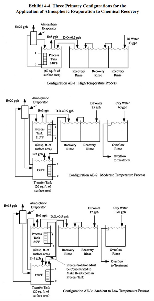
Exhibit 4-4 shows the three basic configurations used for application of atmospheric evaporators for chemical recovery. Application AE-1 is used mostly for elevated process baths (>120°F), AE-2 for moderate temperature baths (100 to 120°F) and AE-3 for ambient or low temperature baths (ambient to 100°F). In each case, an important aspect to the implementation of this technology is the incorporation of recovery rinsing. The quantity of recovery rinse solution that can be added into a bath equals the sum of the evaporation from the tank's surface and the evaporation caused by the atmospheric evaporator (i.e., ignoring any differences in drag-in and dragout). For some processes, where the operating temperature is high and dragout is sufficiently low, a closed-loop configuration can be employed. Several of the respondents to the Users Survey indicated that they have achieved a closed-loop (e.g., PS 003 for nickel, PS 213 for nickel and chrome). Generally, these shops used either a three or four stage recovery rinse. Lower temperature processes and those with high dragout rates will usually require a free running rinse (or countercurrent arrangement) following the recovery rinse tank in order to maintain sufficiently clean water in the final rinse. The effects of rinsing configurations on recovery and plating quality are discussed in detail in Section 3.
The strategy with moderate temperature baths is to connect the atmospheric evaporator to a heated transfer tank with the idea that the solution in the transfer tank can be heated to a higher temperature than the maximum operating temperature of the plating process. For example, a transfer tank used with acid zinc can be heated to 140°F, whereas the maximum operating temperature of the process bath is about 90°F. By connecting the evaporator to the transfer tank, the evaporation rate will be approximately tripled. A number of shops responding to the Users Survey indicated that they were using heated transfer tanks (e.g., PS 098, PS 252 and PS 278).
With low or ambient temperature baths, where there is no appreciable surface evaporation from the process bath, a bleed from the process bath to the transfer bath is used to make the needed headroom. Alternatively, a second evaporator could be used. For some ambient baths that contain wetting agents, drag-in may exceed dragout. The design capacity of the atmospheric evaporator must account for this difference plus the desired recovery rinse rate. In some cases, an atmospheric evaporator may be used simply to create the headroom needed to prevent discarding "extra" plating solution created by these conditions (ref. 355). One such application was found in the Users Survey (PS 214).
The Users Survey also showed that many shops were incorrectly using their atmospheric evaporators. Approximately 20% of the shops connected either an unheated recovery rinse or an unheated plating tank to the evaporator. Generally, these facilities experienced below average results. Performance experience is discussed in Section 4.2.6.
With all applications of atmospheric evaporators, the user should install water treatment in the form of ion exchange and/or reverse osmosis to remove the hardness and other impurities in the raw water that would otherwise accumulate in the process tank.
Recovery applications that were identified during the Users Survey are presented in Exhibit 4-5. The most common recovery application for atmospheric evaporators is nickel plating. On a combined basis, the nickel applications accounted for nearly 30% of all applications (includes bright nickel and electroless nickel applications).
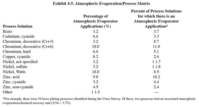
When used in conjunction with hard chrome plating or other processes that have solution heating and cooling requirements and ventilation requirements, the atmospheric evaporator can serve as a recovery unit, cooling device and an air scrubber (ref. 299). Because the unit would be using waste heat from the tank for evaporating excess water, the evaporation process operates essentially free. The appropriate tank configuration is basically the same as shown in Exhibit 4-4, application AE-1. The plating tank's exhaust air would serve as the inlet air to the evaporator, which would remove its chromic acid mist. In such cases, the exhaust of the evaporator is usually connected to the existing ventilation system and the evaporator's blower is eliminated. Because of anticipated regulations for hard chrome plating air emissions, it is questionable that the evaporator's mist eliminator would adequately substitute for a future emission control device. At this time there are insufficient data to evaluate this application.
Atmospheric evaporators are not applicable in cases where the solution temperature cannot be raised above approximately 85°F, either in the process tank itself or in a heated transfer tank. Generally, these are solutions that either contain highly heat sensitive components or fume excessively when heated or aerated. Also, atmospheric evaporators should not be applied to any process solution which cannot be maintained through use of methods and/or technologies that replenish active bath ingredients or remove the contaminants that build-up as a result of recovery rinsing. When applied in these cases, the atmospheric evaporator hastens the disposal rate of the bath resulting in essentially the same mass of chemicals discarded as if recovery were not practiced. Methods of bath maintenance for process solutions are covered in Section 5.
Atmospheric evaporators should not be applied to solutions that foam significantly when air agitated (e.g., high cyanide baths and still nickels). Such solutions will foam in the evaporation chamber and render the system inoperable. A simple jar test is recommended by one manufacturer to determine if foaming is a potential problem. This test is accomplished by placing a sample of the solution in a jar, vigorously shaking it and then observing to see if the foam quickly disappears (ref. Poly Products file).
4.2.4 Technology/Equipment Description
The equipment described in this section is manufactured by four firms that responded to the Vendors Survey. Three of these companies represent approximately 90% of the total number of atmospheric evaporators purchased by the respondents of the Users Survey (not counting home-made units or in cases where the manufacturer was not given).
The manufacture of atmospheric evaporators most often found in the Users Survey data is Poly Products Corporation. They manufacture four different models: ET-II Junior, ET-II, ET-III and ET-III-W. The ET-II Junior, ET-II, and ET-III are progressively larger units of the same design. The ET-III-W has a modified design, intended for use with solutions that have a high solids content. Each model has the same basic appearance and operating principles (refer back to Exhibit 4-3). During operation, pumped solution is circulated at approximately 10 to 45 gpm from the process tank or transfer tank to the unit and is gravity drained back to the tank. In the evaporator, solution is sprayed onto 700 to 1,000 ft2 of evaporative panels to humidify the blower air that is forced through these panels. The air is provided by a blower sized from 1/2 to 1-1/2 hp, depending on the model. The humid air then passes through a chevron mist eliminator to remove entrapped chemical solution droplets and is ducted to the outdoors. Poly Products offers an optional mesh pad mist eliminator to further decrease chemical emissions. The ET units are manufactured of molded polyethylene. The largest ET unit occupies a floor space of 48 in. x 34 in. All models have maximum air temperature limits of 104°F and solution limits of 160°F (ref. Poly Products file).
Techmatic Inc. manufactures the MAX-EVAP™. There are four models available: MAX-EVAP, Super MAX-EVAP, MAX-EVAP Cr and Super MAX-EVAP Cr. The MAX-EVAP and Super MAX-EVAP are general purpose units with advertised evaporation rates of 50 to 60 gph and 80 to 90 gph, respectively. The bodies of these units are manufactured from polyethylene. The MAX-EVAP Cr and Super MAX-EVAP Cr are designed specifically for hexavalent chromium plating solutions. These two models are manufactured from steel and are lined with Koroseal (PVC). As with the operation of the Poly Products line, solution is circulated from the process tank or transfer tank to the unit and is gravity drained back to that tank. In the evaporator, solution is sprayed onto 5 to 10 ft3 of polyethylene packing. Air is drawn through the unit by the shop's existing ventilation system or air movement is provided by an optional blower. The exhaust air passes through a "vertical extruded mist eliminator" (not defined by manufacturer) to remove chemical mists. The MAX-EVAP unit occupies a floor space of 63 in. x 21 in. and has a height of 31 in. (blower option measures 55 in. high) (ref. Techmatic file).
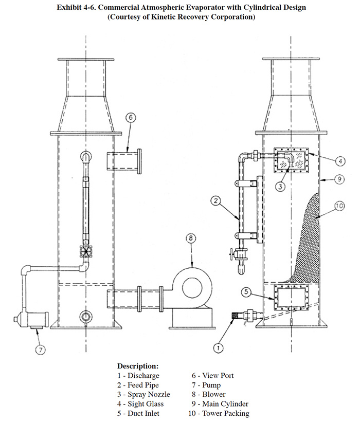
Kinetic Recovery manufactures a unit with a somewhat different design than the two previously discussed units. With the Kinetic Recovery unit (Exhibit 4-6) the process solution is pumped from its tank up to the liquid distributor of the evaporator which is located at the top of the cylinder. The liquid trickles over a tower packing down to the bottom drain of the cylinder and returns to the process tank. A blower, located at the bottom of the cylinder, blows air (300 cfm) upward through the packing to the top of the evaporator. When the air goes through the packing (pressure drop 0.3 in. of superfacial vapor velocity of 1.5 fps) it becomes saturated with vapor from the process solution. The cylindrical design improves air flow distribution by reducing dead space. On the top of the cylinder there is a vent transition which contains a mist eliminator (12 in. flexichevron). There are two view ports located on the unit, one at the liquid distributor and another below the packing. The basic Kinetic Recovery unit is manufactured from polypropylene and they offer construction in PVDF. The PVDF unit operates with a maximum solution temperature of 180°F.
NAPCO manufactures atmospheric evaporators with two basic designs: (1) cross-flow air pattern and (2) vertical air flow pattern. Both types of units are normally constructed of polyethylene, but a variety of plastics are also available, depending on the customers needs. The basic NAPCO unit consists of a blower, recirculation pump, high surface area packing and demister baffling. Numerous options are available, including heating coils, temperature controls, level controls and make-up solenoids and pumps. Their standard size units range from 10 gpm process feed/1,200 cfm air flow (NAPVAP Jr) to 30 gpm process feed/4,000 cfm air flow (NAPVAP Sr). NAPCO has been marketing their equipment to the plating industry since 1985 and have sold approximately 160 units to 100 different plating shops.
For each of these four commercial evaporators, the heat used for evaporation comes from the plating or transfer tank (unless a heating coil option is specified). Heat taken from the plating bath must be replaced by the tank heating system (e.g., immersion heaters or steam system) in order to maintain the operating temperature of the bath. Most tank heating systems are designed to provide a quick heat-up and are underutilized after the operating temperature is maintained. Therefore, auxiliary tank heating equipment is usually not necessary when an atmospheric evaporator is installed (unless a transfer tank is also installed). However, each potential installation should be evaluated before purchasing evaporative equipment. Nomographs and methods of calculating tank heating requirements are available in electroplating engineering references (e.g., ref. 341).
The atmospheric evaporators previously discussed are used primarily for chemical recovery, but are occasionally applied to waste concentration. Some evaporators are designed specifically for waste concentration. Two such units include the Technotreat Wastewater Evaporator and the Samsco Water Evaporator.
The Technotreat unit consists of an enclosed carbon steel (stainless steel available) tank equipped with electric immersion heaters (stainless steel or titanium). Liquid waste is fed into the evaporator by a feed pump from a drum or storage tank. The solution level in the evaporator is maintained by a level switch which activates the feed pump. The steam is vented by an assisting electric blower. As water is evaporated, the waste is concentrated. Oil floats to the top and is drawn off periodically. Sludge and viscous materials are removed through a bottom drain. The Technotreat unit comes in 100 and 200 gpd capacities. The range of costs is approximately $10,000 to $15,000 for the standard materials of construction (ref. 360).
The SAMCO Water Evaporator combines direct heating and air flow. The unit consists of an enclosed tank (carbon steel or 304 or 316 stainless steel) that contains a serpentine gas-fired heat exchanger and blower (530 cfm to 2,000 cfm) that draws air in through both the burner and an opening in the top of the tank. In operation, solution is fed to the tank in either a batch or continuous mode. The solution is heated to boiling (approximately 212°F) by the heat exchanger. The action of the blower draws air across the surface of the heated liquid, sweeping away water vapor as it breaks to the surface. The moisture-saturated air and the flue gases leave the tank via separate passages and are joined together at the blower entrance. The two air streams are mixed in the blower and released up a stack. Free oils that float on the surface of the liquid overflow a trough into an external waste receptacle. Solids that settle onto the sloping bottom of the tank are removed via a clean-out port. The SAMCO Water Evaporator comes in three capacities: 15 gph, 33 gph and 63 gph. The area dimensions of the largest unit are 65 in. x 68 in.
Installation of an atmospheric evaporator is a relatively easy task with the exception of the ventilation ducting. The basic units are shipped prepiped and preassembled. For ventilation, ductwork is usually routed directly to the outdoors through a roof penetration. Alternatively, the exhaust of the evaporator can be connected by ductwork to an existing ventilation system. In this case, an evaporation system blower is unnecessary and the air would be drawn through the evaporation chamber rather than being pushed or blown through. As discussed in Section 4.2.3, this configuration is occasionally used with hard chromium plating.
Installation and operation of an atmospheric evaporator may require a new air permit or revisions to an existing air permit.
4.2.5 Costs
4.2.5.1 Capital Costs
The basic equipment cost for atmospheric evaporators is relatively low. However, all installations will experience some installation costs and most installations will require auxiliary equipment. The most common and significant installation cost is for exhausting the air exiting the evaporator. Ductwork must be run to either to an existing ventilation duct or, more frequently, through a roof penetration. Other installation work includes connecting power and water to the evaporator, rearranging of other equipment or tanks, installation of controls and installation of a transfer tank. Auxiliary equipment may include, for example, a transfer tank, additional recovery rinse tanks, an additional heat exchanger or a DI water system.
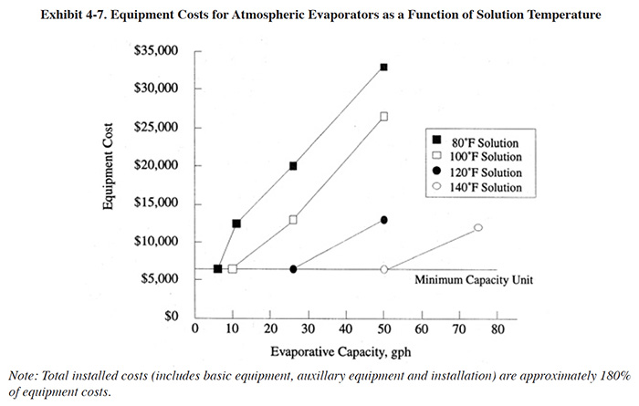
Capital cost estimates for atmospheric evaporators are shown in Exhibit 4-7. These costs are presented as a function of evaporative capacity (gph) over a range of process solution temperatures (either the process tank or transfer tank, whichever is fed to the evaporator). Exhibit 4-7 shows the basic equipment costs, which were derived by taking the median costs from the three vendor survey respondents (where a single evaporator is unable to provide the desired evaporation capacity, multiple units were assumed). The installed capital costs are approximately 180% of the basic equipment costs (based on Users Survey data).
4.2.5.2 Operating Costs
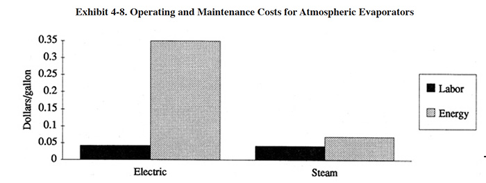
The major operating costs for atmospheric evaporators include O&M labor and energy. Estimates of these operating cost components are shown in Exhibit 4-8. From the Users Survey, the average O&M labor is 157 hrs/yr. In constructing the operating cost graph, it was assumed that this level of labor is adequate for a unit evaporating 15 gph, 24 hrs/day for 260 day/yr. The energy cost shown in Exhibit 4-8 is for replacement heat in the process tank and for operating a pump. The energy cost does not account for energy loss due to ventilation of shop air during winter months.
 |
 |
4.2.6 Performance Experience
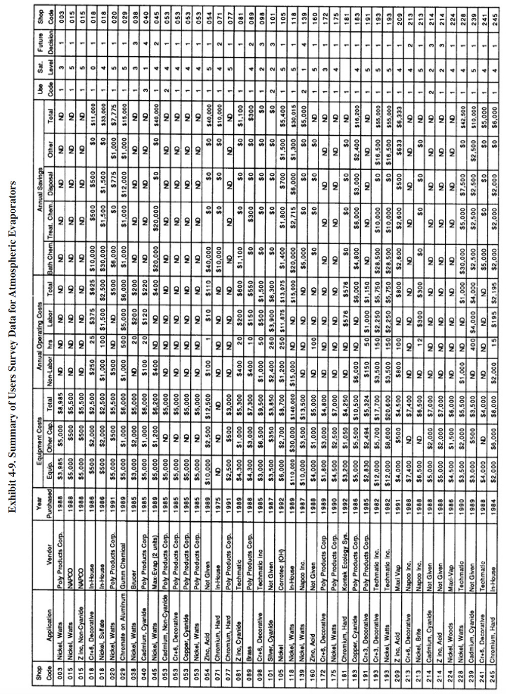
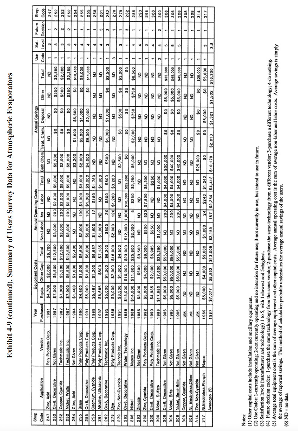
A partial summary of the NCMS Users Survey data relative to atmospheric evaporators is presented in Exhibit 4-9. There are a number of observations that can be made from these data and other data contained in the database and literature:
- The majority of shops that have used atmospheric evaporators have found them to perform adequately. The average
satisfaction level for this technology is 3.8 (on a scale of 1 to 5, with 5 being most satisfactory), which is
the highest level rating for any of the chemical recovery technologies, except for meshpad mist eliminators.
Also, 81 percent of the shops indicated that this technology satisfied the need for which it was purchased. The
following is a breakdown of the reasons why shops purchased this technology:
To meet or help meet effluent regulations: 46 To reduce plating chemical purchases: 45 To reduce the quantity of waste shipped off-site: 39 To reduce wastewater treatment costs: 35 To improve product quantity: 9 Other: 6
- The use of atmospheric evaporators generally did not impact production quality or the rate of production. The following responses were provided:
Product Quality Production Rate Improved 7 3 No Change 52 53 Decreased 6 9
- Where the product quality was impacted (PS 098, PS 118, PS 139 and PS 306), PS 098 and PS 139 indicated that contaminant buildup occurred in their chromium plating and nickel plating baths and PS 118 indicated that product quality is only impacted occasionally due to low rinse water flows.
- Where the production rate was impacted (PS 098, PS 139, PS 252, PS 262 and PS 306), PS 098 and PS 252 attributed work slowdowns to bath contamination.
- Most plating shops indicated, that based on their experience with this technology, they would pur-chase the same type of equipment from the same vendor. The following is a breakdown of their responses:
Purchase the same technology from the same vendor: 73% Purchase the same technology from a different vendor: 12% Purchase a different technology: 12% Do nothing: 3%
- The reported savings from use of atmospheric evaporators was mostly due to reduced purchases of plating chemicals. The average annual savings per shop were slightly less than the sum of the average capital costs plus annual operating costs. This indicates, that on the average, shops experienced a payback period of approximately one year.
- Very few survey respondents reported the evaporation rate they were achieving with their atmospheric evaporator. Presumably, this is because such data are not routinely collected. The highest evaporation rate reported by a respondent was 60 to 75 gph (PS 183). Oddly, with this particular application, the shop connected the evaporator to a heated, 150°F cadmium cyanide transfer tank.(This is not a recommended application because heating of the cadmium solution will destroy cyanide and create carbonates.) PS 183 indicated in their survey form that they would have achieved a closed-loop "if it were not for the carbonate problem." For more traditional applications (nickel and chrome operated at 130 to 140°F), the highest reported evaporation rates were in the range of 20 to 50 gph (e.g., PS 228, PS 213).
- Some of the plating shops that gave atmospheric evaporation a lower rating may have misapplied the technology. The most frequent misapplication is the use of this technology for the concentration of ambient temperature process solutions or drag-out. The commercial units do not have a direct heat source, but rather use heat from the process or transfer tank to evaporate water (see complete explanation in Section 4.2.1). When applied to an ambient solution, very little evaporation will take place. For example, PS 081 attains an evaporation rate of only 3 gph from a unit connected to a zinc cyanide bath that is operated at 85°F. PS 279 attains a rate of 2 to 5 gph for an ambient acid zinc application. Other plating shops that may have misapplied the technology include (based on a review of supplied schematics): PS 040, PS 045, PS 101, and PS 143.
- The high incidence of misapplication for this technology may be due in part to the fact that 54%of the
commercial atmospheric evaporators purchased by survey respondents were sold to them by manufacturer's
representatives rather than direct purchases. The manufacturer's representatives may not have had sufficient
knowledge of the technology to recommend proper installation.
In some cases, performance was hampered by operational and maintenance problems. These are discussed in Section 4.2.7.
4.2.7 Operational and Maintenance Experience
The following summarizes the respondents O&M experi-ences and provides operating labor information relative to atmospheric evaporators.
- The quantity of labor required for the operation of this technology is relatively low compared to other recovery technologies. For shops providing data, the average number of annual operating hours per evaporator were: 157 hours per year. The skill requirement commonly needed for operating this technology is a trained technician, a wastewater treatment system operator, a plumber/pipe fitter or common labor. The following is a breakdown of the responses for skill requirements:
Environmental Engineer: 0 Process/Chemical Engineer: 3 Chemist: 5 Consultant: 0 Plumber/Pipe Fitter: 15 Electrician: 9 Vendor: I Senior-Level Plater: 8 Junior Level Plater: 11 Trained Technician: 24 Wastewater Treatment Plant Operator: 16 Common Labor: 16
- Approximately 90 percent of the atmospheric evaporator installations identified in the Users Survey were in operation at the time of the survey. The following is a breakdown of the responses for current operating status:
Currently in use: 89.6% Not currently in use & have no intention of future use: 7.5% Not currently in use, but intend to use in the future: 3.0%
- The average percent of downtime experienced with this technology was 7%. Only 15 percent of the respondents indicated that their downtime was greater than 5% (those with greater than 5%downtime included: PS 045, PS 101, PS 105, PS 139, PS 213, PS 239, PS 282, PS 298, PS 300 and PS 317).
- Generally, this technology is free of complex mechanical operational and maintenance problems because of the simple design and limited number of moving parts. There are however, some common maintenance requirements, most of which relate to cleaning. A list of the most frequently reported maintenance requirements follows (the percentage of all respondents identifying the problem is given in parenthesis):
Cleaning of evaporation chamber packing or evaporative panels: 11% Cleaning of nozzles that spray solution over packing or evaporative panels: 4.7% Maintaining pumps: 4.7% Unplugging of pipes: 1.6% Maintaining timers: 1.6%
- Fifty-seven percent of the plating shops that reported cleaning as a maintenance item have purchased the units equipped with evaporative panels rather than the plastic packing. The company that manufactures the panel-type unit has recently introduced a model that is designed to better handle high solids conditions (see 4.2.4). In some cases, the cleaning requirement was blamed on carbonates that precipitated from aerating cyanide containing solutions in the evaporator (PS 089, PS 101, PS 239, PS 258). In two other cases, crystals that formed from the drying of plating chemicals were blamed (PS 045, PS 172).
- According to the literature, plating chemical crystals can be removed from the packing and nozzles by a weekly recirculation of hot water through the evaporator with the fan shutoff. Salts that have formed on the nozzles and packing will dissolve (ref. 355). Carbonate deposits present a more significant problem and most likely will require mechanical (e.g., scraping) removal.
- One shop indicated that operation of their atmospheric evaporator for chromium plating solution recovery resulted in degrading of the unit and piping and that the manufacturer has replaced their evaporator twice in the past five years (PS 252). This shop also operates units for cyanide copper and nickel plating and has not experienced any problems with these other units. A leaking problem around welds was reported by another shop (PS 300). Eventually, PS 300 discontinued use of three of their atmospheric evaporation units because of leaking.
- Many shops indicated that use of an atmospheric evaporator has caused a build-up of contaminants in the plating bath. The most frequently identified problem was carbonate build-up in cyanide containing baths such as zinc, cadmium and copper (ref. PS 081, PS 089, PS 183). Respondents also indicated problems with contaminant build-up in chromium baths (PS 089, PS 172, PS 252 and PS 255), and nickel baths (PS 038, PS 105 and PS 139). PS 139 reported a build-up of brightener and iron in their nickel bath. Twice PS 139 has tried evaporative recovery for nickel and abandoned their efforts.
- Other bath problems attributed to use of an atmospheric evaporator include a breakdown of nickel bath chemicals (PS 039) and increased bath chemistry maintenance for trivalent chromium plating (PS 191).
- Several shops reported that climatic conditions effect the evaporative capacity of their atmospheric evaporator (PS 160, PS 183 and PS 224). These three shops are located in different regions (survey regions SE, FW and MW).
4.2.8 Residuals Generation
Most shops using atmospheric evaporators did not report the generation of any residuals. Presumably, this is because most residuals that would form in the evaporator (e.g., carbonates) will, for the most part, gravity drain back to the process tank. Two shops that reported residuals from the evaporator were PS 089 and PS 113. PS 089 uses a home-made evaporator for chromium solution recovery and generates a "minimal" quantity of sludge. PS 089 generates 30 gal/mth of sludge from evaporative recovery of cadmium solution.
Several other shops listed the carbonates removed from their cyanide containing plating solutions as a residual generated by evaporation. Presumably, they feel that the evaporator created this waste product. The most significant quantity is generated by PS 183 (80 lbs/week).
4.3 VACUUM EVAPORATORS
4.3.1 Overview
Vacuum evaporators are one of the earliest technologies used in the plating industry for chemical recovery. However, vacuum evaporators are currently used less frequently than some other recovery technologies, such as atmospheric evaporators (see Section 4.2). This is primarily due to the fact that the average vacuum evaporation unit costs approximately ten times more than the average atmospheric unit. Also, the vacuum units have more sophisticated and expensive operational and maintenance requirements. Of the 318 plating shops responding to the Users Survey, 23 shops (or 7.2%) have employed vacuum evaporators (30 total units of which approximately 80% were still in operation at the time of the survey) for chemical recovery, whereas, 71 shops (or 22.3%) have used atmospheric evaporators (86 total units). Another six shops (or 1.9%) use vacuum evaporators as end-of-pipe technologies to concentrate their wastes prior to off-site hauling and disposal. This section discusses recovery applications of this technology and Section 7.4.4 addresses end-of-pipe applications.
A vacuum evaporator is a distilling device that vaporizes water at low temperatures when placed under a vacuum. The following explanation of the kinetic theory of liquids and in particular vapor pressure helps in understanding this phenomena.
Liquids as well as gases are in constant motion in varying degrees, depending upon the chemical composition of that matter and the temperature and pressure applied to it. Molecules near the surface have a tendency to escape into the surrounding atmosphere. In open systems, most of these molecules do not return to the liquid and the substance is said to vaporize. In a closed system, molecules return to the liquid in proportion to their concentration in the gaseous phase. Eventually a steady state is reached where the quantities of molecules leaving and returning to the liquid are equal. The vapor is then said to be saturated and the pressure exerted by these escaping molecules is referred to as vapor pressure (ref. 361). Since the kinetic energy of all molecules increases with increasing temperature, so does the vapor pressure. When a liquid reaches the temperature at which its vapor pressure becomes equal to that of the atmosphere above it, boiling occurs. This is the rapid evaporation from all parts of the liquid mass, with bubbles of vapor forming in the interior and rising to the surface. Liquids with appreciable vapor pressure may be caused to boil over a wide range of temperatures by decreasing or increasing the pressure of the atmosphere above it (ref. 362). For example, water boils at 212°F at sea level, but will boil at room temperature if the pressure above it is reduced to about 0.4 psi (ref. 361).
Vacuum evaporators depend on the fact that water, when introduced into a vacuum, tends to boil off, or vaporize. The rate of vaporization is directly related to the level of the vacuum and the temperature of the solution. In operation, heated solution is introduced into the vacuum chamber, the boiling point of the solution is reduced by the vacuum and the resultant vapor (distilled water) is removed from the chamber. The vapor can be either discharged or can be condensed for return to the process (e.g., as rinse water).
Vacuum evaporation systems are relatively complex and are therefore more expensive to construct and maintain than the more simple atmospheric systems discussed in Section 4.2. There are several types of vacuum evaporators used in the plating industry: rising film, flash type, and submerged tube. Generally, each consists of a boiling chamber which is under a vacuum, a liquid/vapor separator and a condensing system. Site-specific conditions and the mode of operation influence the selection of one system over another.
Two techniques have been applied successfully to reduce steam demand for evaporation; both involve reusing the heat value contained in the vapor from the separator. The most common technique is to use a multiple-effect evaporator. Essentially, these are vacuum evaporators in series with different boiling points, made possible by varying the pressure between effects (subsequent effects have lower pressures). The driving force of a multiple effect system is the pressure drop from the first to the last effect. The solution to be concentrated is fed into the boiling chamber of the first effect and external heat is introduced to volatilize the water. The water vapor is then condensed at a different vacuum level and the energy is used to heat the subsequent vacuum chamber. Therefore, the same energy is used several times in multiple stages.
The second technique is to use a mechanical compressor. With this equipment, the water vapor from the separator enters the suction of the compressor where its temperature and pressure are increased. The vapor is then desuperheated and enters the reboiler. Thus the latent heat of evaporation, normally lost to the condenser is recycled by the compressor, providing a temperature difference across the heat exchanger. The needed energy then comprises only the power for the pressure increase to provide the temperature difference.
There are a number of advantages accruing to vacuum systems. Among them are the fact that they are essentially independent of the requirement to heat and move large volumes of air, thus reducing the air pollution problem, at least when compared to atmospheric systems. Further, they are operated at relatively low temperatures, which could be of considerable importance in systems that handle temperature-sensitive products. Additionally, vacuum systems are advantageous with alkaline cyanide solutions which would build up carbonates more rapidly with atmospheric evaporators because the latter type aerates the solution.
4.3.2 Development and Commercialization
Evaporation has been used for centuries for food and beverage processing. Modern vacuum evaporator design for industrial use dates back to the early 1900's with the development of the rising film evaporator. Plating applications for vacuum evaporators began in approximately 1949, when systems were used to recover chromic acid (ref. 300). The early plating applications were purchased primarily to reduce operating costs through chemical conservation. Subsequently, evaporation was sporadically implemented as a pollution control method in response to local discharge standards. In some cases, this was a sufficient method of meeting the local standards for targeted pollutants such as cyanide and chromium. The early evaporators used for plating applications were the same types of units used by other industry segments (e.g., chemical processing, dairy, food and beverage industries). These units had large capacities, due in part because water conservation and pollution control were less important at the time, resulting in higher flow rates. Also, energy was much less expensive. In 1974, with the advent of rapidly rising energy costs, there began a movement to down-size recovery systems. Coupled with the Federal pollution control standards, first promulgated in 1979, plating shops turned to smaller and more energy efficient vacuum evaporators and the less expensive atmospheric evaporators for chemical recovery. Energy efficiency was achieved by the employment of multi-effect vacuum units and mechanical vapor compression. During the 1980's and early 1990's firms have sought methods of low or zero effluent discharge to reduce their regulatory requirements. As a result, the newer energy efficient vacuum evaporators were applied as end-of-pipe technologies (ref. 300, 375).
There are approximately 25 companies that manufacture and/or supply evaporative recovery equipment applicable to the plating industry. This includes vacuum and atmospheric evaporators for both chemical recovery and waste concentration (ref. 421). Of these companies, three firms have responded to the vendors survey (LICON, Inc., Calfran Int., and QPS Inc.).
4.3.3 Applications and Restrictions
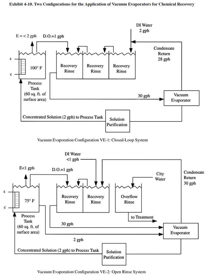
Two common configurations for the application of vacuum evaporators to chemical recovery are shown in Exhibit 4-10. In configuration VE-1, a closed-loop process is achieved using a three stage rinse system with the feed from the first rinse being concentrated by the evaporator and directed to the plating bath. A solution purification step is shown, which removes bath contaminants that would buildup in the bath due to the closed-loop process. Typical solution purification technologies used for this purpose include ion exchange and/or carbon filtration. PS 125 employs this configuration using a cation exchange unit to remove contaminants from its decorative chromium plating rinse water/dragout. PS 124 has a similar arrangement. PS 082 installed a cation exchange unit and electrolytic purification unit that are connected to a storage tank. The use of multiple-stage rinsing is nearly always required with evaporator applications in order to minimize the quantity of water to be evaporated.
The survey respondents used a minimum of two and a maximum of four rinsing stations. The second configuration (VE-2) shows an open process, where a small portion of the dragout is not recovered. Also shown in VE-2, is a direct bleed from the bath to the evaporator. This may be required for ambient or low temperature baths, where there is a limited surface evaporation rate and insufficient "head-room" in the plating tank to return the concentrated dragout/rinse water.
Vacuum evaporators are applied to the recovery of a wide range of plating solutions. They are especially applicable in situations where atmospheric evaporators are either technically or economically impractical. This includes: (1) the recovery of heat sensitive chemicals (e.g., cyanide plating baths); (2) the recovery of chemicals that are sensitive to air oxidation (e.g., cyanide plating baths or the stannous tin bath); (3) low or ambient temperature plating solutions where there is no appreciable surface evaporation; (4) the recovery of solutions that contain volatile components; and/or (5) where high evaporation rates (e.g., >20 to 40 gph) are necessary to achieve recovery and atmospheric evaporators become too expensive (i.e., energy cost) to operate (ref. 299).
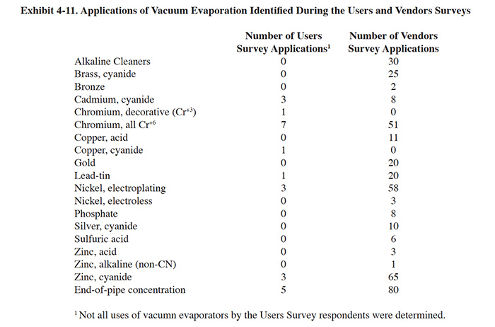
The results of the Users Survey and Vendors Survey showed that vacuum evaporators are applied to a range of plating and finishing solutions. These identified applications are shown in Exhibit 4-11.
Although vacuum evaporators may provide an energy savings over the atmospheric types of evaporators, neither one is economically practical to purchase or operate where large volumes of low concentration solutions are involved. In those cases, ion exchange or reverse osmosis are the more cost effective methods of recovery (ref. 299).
4.3.4 Technology/Equipment Description
4.3.4.1 General
This subsection discusses commercially available vacuum evaporation equipment that is manufactured and/or sold by vendor survey respondents. This is intended to provide the reader with information and data on a cross section of available equipment. Mention of trade names or commercial products is not intended to constitute endorsement for use.
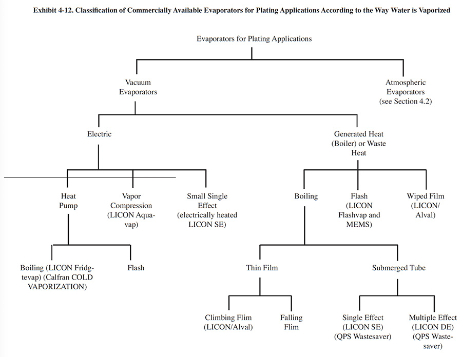
There is a wide range in design of vacuum evaporators, although the majority of these devices work on the principles described in Section 4.3.1. Vacuum evaporators are built by various manufacturers for different applications. Exhibit 4-12 classifies vacuum evaporators according to the way water is vaporized. This design element helps to differentiate between some of the commercial equipment available to the electroplater. It should be noted that not all manufacturers of plating evaporation equipment are represented in this exhibit.
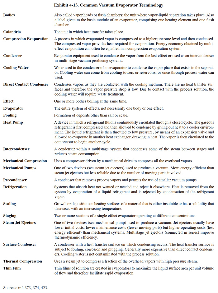
As with any technology group, the vacuum evaporation industry has developed their own terminology for their equipment and its components. Some of their commonly used terms are defined in Exhibit 4-13.
The following subsections describe the types of vacuum evaporators that are applicable to the plating industry. Where information is available, specific commercial units are briefly described.
4.3.4.2 Submerged Tube Evaporators
The submerged tube evaporators, which includes the short and long tube vertical (LTV) types and the horizontal tube type, are termed natural circulation evaporators, because no pump or other recirculation device is employed. These units, which are older, but still widely used types of vacuum evaporators, are sometimes referred to as calandria type evaporators. With the basic design (short tube type), a vertical tube bundle is placed inside a vertical cylindrical evaporator shell. The tubes or tube sheets, usually two to six feet in length, span the body diameter. The liquid level in the body is typically maintained such that 50% of the tube sheets are immersed. Liquid circulates through the tubes at a rate many times greater than the feed rate. The liquor travels up through the tubes and down a central pipe called a "downcomer." Steam or water vapor condenses on the outside surface of the tubes and the liquor is heated and boiled inside the tubes. The circulation of the liquid is achieved because of the difference in specific gravity between the liquor and vapor in the tubes plus a vapor lift effect. This combined phenomenon is known as the thermosyphon effect and it is the design basis for all natural circulation evaporators, which includes the falling film types (ref. 376, 422, 423). In some cases, an agitator, located inside or beneath the downcomer, is used to increase circulation in salting-type applications.
Generally, the submerged tube evaporators are less expensive to purchase than rinsing film or flash units of equal capacity. Steam or thermal demand is the same as for rising film (ref. 376). The evaporators find application for processing mildly scaling liquors and relatively viscous solutions (ref. 422).
LICON Inc., a manufacturer of electroplating evaporation equipment and a Vendors Survey respondent, manufactures single effect and double effect submerged tube evaporators. These devices have been applied to the concentration of chromium (Cr+3 and Cr+6), zinc chloride, nickel chloride, nitric acid, and sulfuric acid bearing waters as well as mixed waste streams (ref. LICON file).
QPS manufactures the Wastesaver® submerged tube evaporator, which is available with either single, double or triple effects. Their newer units have a pumpless liquid transfer system that reportedly eliminates problems commonly associated with mechanical liquid transfer equipment (e.g., pumps, seals, impellers, etc.). These units are manufactured with capacities ranging from 25 gph to 1,500 gph. The basic units are manufactured from stainless steel with titanium offered as an option.
4.3.4.3 Rising Film (Climbing Film)
The basic rising film evaporator consists of an evaporator body, separator and condenser. The evaporator body is a shell-and-tube heat exchanger. Liquid feed enters the bottom of the heat exchanger, it is preheated until it reaches the boiling point and it then moves up the tube. The vapor generated occupies the center of the tube and the liquid is forced to the tube wall. As the fluid travels up the tube, more vapor is formed resulting in a higher central core velocity. The upward velocity of the vapor forces any remaining liquid to the tube wall and continues to provide an upward motion. As the process continues, the higher vapor velocities result in thinner and more rapidly moving liquid films. This design provides a high heat transfer coefficient and relatively short residence time (ref. 373, 375, 376).
Evaporation is typically accomplished at pressures of 1.3 to 7.5 psia (67 to 388 mm Hg absolute), thereby lowering the boiling point to 110° to 180°F (43° to 82°C). The wastewater leaves the body and enters the separator where the water vapor is separated from the heavier plating solution. The plating solution is either returned directly to the bath or held in an integral reservoir. The vapor leaving the separator is condensed in a shell-and-tube heat exchanger and the distillate is directed to the rinse tanks (ref. 376).
Commercially available rinsing film evaporators used in the plating industry are manufactured by LICON/Aval and Corning. Several existing plating applications of rinsing film evaporators identified in the Users Survey were manufactured by the Pfaudler Company.
4.3.4.4 Falling Film
Liquid enters the top of the evaporator and a liquid film is formed by gravity, which then flows down the heat transfer surface. During evaporation, vapor fills the center of the channel and as the momentum of the vapor accelerates, the film becomes thinner. Also, the solution accelerates in velocity as it descends inside the tubes because of gravity and the drag of the vapor. Since the vapor is working with gravity, a falling film evaporator produces thinner films than a rising film evaporator for any given set of conditions. This gives rise to shorter residence times and a further improvement over the rising film types in heat transfer. With these devices, liquid is usually separated from the vapor in the bottom liquid chamber of the body.
The falling-film evaporator is particularly useful in applications involving heat sensitive chemical solutions. This is due to a low "driving force" or temperature difference between the heat-transfer medium and the liquid (∆T's less than 15°F compared to 25°F or more for the rising film) (ref. 375, 377).
No commercial electroplating applications of the falling film evaporator were identified during the Users or Vendors Surveys, although they presumably exist due to the widespread commercialization of these devices (ref. 373, 377).
4.3.4.5 Wiped Film Evaporator
Feed is introduced at the top of the evaporator and is spread by wiper blades on to the vertical cylindrical surface inside the unit. Evaporation takes place as the thin film moves down the evaporator wall. The heating medium is usually high pressure steam. Use of the wiped film evaporator is limited primarily to highly viscous liquids and the stripping of solvents. The high number of moving parts, such as the rotor and wiper blades, may result in higher maintenance costs than other types of evaporators (ref. 375).
LICON Inc. manufactures a wiped film evaporator (Strat-avap) with capacities from 5 to 700 gph, but no plating shop applications were identified in the Users or Vendors Surveys for this device or other wiped film evaporators.
4.3.4.6 Flash Evaporators
Unlike with thin film types (e.g., falling film or wiped film), with flash evaporators, vaporization does not occur on the heat exchanger surfaces. Instead, liquor flashes as it enters a separator, crystallization takes place, and a suspended slurry results. Since evaporation does not take place on a heat transfer surface, the tendency for scale to deposit is significantly reduced. The flash evaporation system can be used in single or multiple effects.
The LICON Inc. Flashvap is sold as an end-of-pipe industrial waste concentrator.
4.3.4.7 Thermal Compressor Evaporators
The thermal compressor evaporators are not, by themselves, a separate category of evaporator. Rather, they are evaporators, such as a rising film type, that uses a steam jet ejector or thermocompressor in order to increase steam economy. They can be designed with either single or multiple effects, although the thermocompressor is normally used on a single effect evaporator or only on the first effect of a multiple effect evaporator. Typically, the addition of a thermocompressor will provide an improved steam economy equal to the addition of another effect, but at lower cost. They should be considered only when high pressure steam is available. Because of their smaller size in comparison to an additional effect, they are favored in applications where space limitations exist. A disadvantage of these units is that the condensate is sometimes contaminated with product traces and may have to be treated, rather than reused as rinse water.
No applications of thermal compression were identified during the Users or Vendors Survey.
4.3.4.8 Heat Pump Evaporator
A heat pump is a device that upgrades a heat source to a higher temperature, thus rendering it more useful. With conventional evaporator/heat pump operation, a refrigerant, upon boiling, absorbs the heat that would otherwise be rejected in a condenser. The refrigerant vapor is compressed to a pressure adequate to permit the vapor to be condensed in the calandria, thereby providing the heat needed for evaporation. The condensate from the calandria is flashed into the condenser, thereby completing the cycle (ref. 373). The heat pump eliminates the waste of single and double effect designs, but does cost electrical power to operate the heat pump. Therefore, it is not applicable to plating shops where waste heat is available. Also, it is generally confined to small flows (≤ 100 gph) due to the range of heat pumps available.
LICON Inc. manufactures the Fridgevap (3 to 100 gph) heat pump evaporator, in which the solution is evaporated at around 100°F (40°C). This unit finds application where heat sensitive chemicals are involved.
Calfran, Int. manufactures a line of heat pump evaporators that they term COLD VAPORIZATION™. These include the PTU series (immersion coil design) and STU series (reaction vessel type) for applications of 1,000 gpd or less and greater than 1,000 gpd, respectively and the VTU series designed for low solids feed streams (75 to 1,000 gpd). Their basic materials of construction include 316 stainless steel heat exchangers and PVC shells. Their units are also available in all stainless steel design and heat exchangers are available in titanium and Hastelloy.
4.3.4.9 Mechanical Vapor Recompression (MVR)
The MVR evaporator is the highest priced evaporator type used in the electroplating industry and it is also the most energy efficient. The MVR evaporator is similar to a conventional single-effect evaporator, except the vapor released from the boiling solution is compressed (adds energy) in a mechanical compressor. This compressed water vapor condenses and gives up its latent heat, which is used to vaporize more water from the liquid that is being concentrated. The following example from the literature shows the potential operating cost savings from using the MVR evaporator (ref. 375).
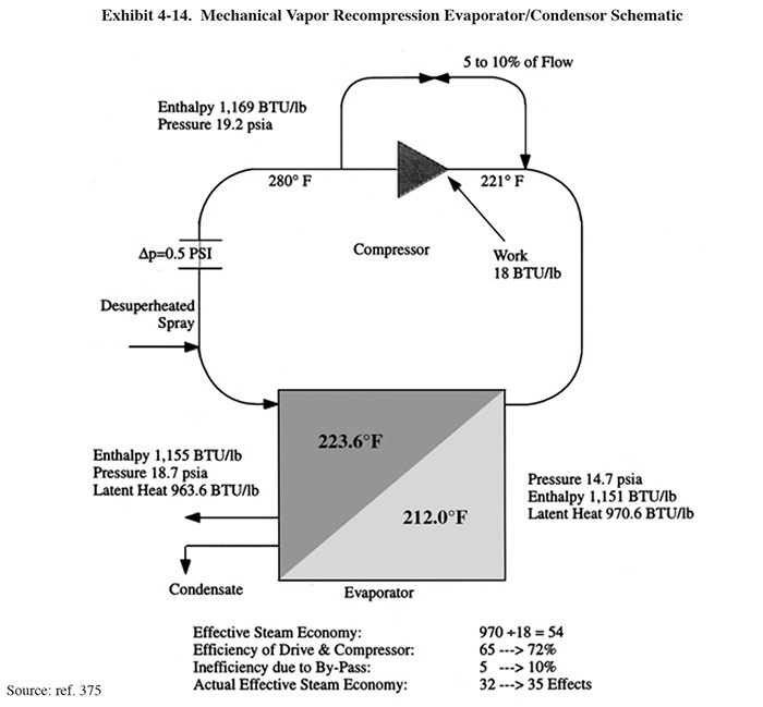
Exhibit 4-14 shows an evaporator with a liquid boiling point of 212°F (atmospheric pressure). All of the water vapor that is boiled off passes to a compressor. In order to keep the energy input to the system as low as possible, the pressure boost across the compressor is limited. In the majority of cases, this pressure boost will correspond to a saturated temperature rise in the region of 15°F or less. In this example, there is a pressure boost of 4.5 psi across the compressor. Assuming that there is a pressure loss of 0.5 psi in the system, the effective pressure on the steam side of the evaporator is 18.7 psi. This compressed water vapor condenses and gives up its latent heat, which is used to vaporize more water from the liquid that is being concentrated. The latent heat of vaporization of water at atmospheric pressure is 970 Btu/lb. Note that it only requires a theoretical energy input of 18 Btu/lb to raise the water vapor from 14.7 to 19.2 psia. The theoretical steam economy, therefore, is 970/18 = 54. When compressor efficiency is taken into account, this figure is brought down to between 32 and 35 which is another way of saying that the MVR system is equivalent to an evaporator with 32-35 effects (see definitions in Exhibit 4-13). However, when the electricity cost for the compressor drive is taken into account, the MVR system then becomes the economic equivalent of just under a 19 effect evaporator.
The MVR has another definite advantage over steam. The condensate is available at high temperature and is ideal for evaporator feed preheating, particularly if the condensate rate is as high as 90% of the feed rate, i.e., a 10:1 concentration ratio within the evaporator. There are many such evaporators in operation where the sole energy input to the system is through the compressor with steam requirements limited to approximately 15 minutes during start up (ref. 375).
An example of a commercial MVR evaporator used by the plating industry is the LICON Inc. Aquavap. This evaporator has an auxiliary flash stage and is capable of achieving concentrations of 500,000 mg/l or more. Evaporative capacities for the Aquavap range from 50 to 600 gph. Existing plating applications include: concentrations of zinc phosphate rinses (multiple units totaling 1,800 gph), concentration of RO reject (300 gph), and end-of-pipe wastewater concentration (50 to 600 gph) (ref. LICON Inc. file).
4.3.4.10 Multiple Effect Evaporators
Multiple effect evaporators are not a specific type of evaporator, but rather a design element employed to improve the energy efficiency of the evaporation process.
Most evaporators used in the plating industry are single-effect units. Single-effect evaporators operate with one boiler or evaporator section. The water vapor is condensed or exhausted to the atmosphere. Approximately 1.1 pounds (0.5 kg) of steam is consumed in evaporating each pound of water from the plating solution (ref. 376).
 |
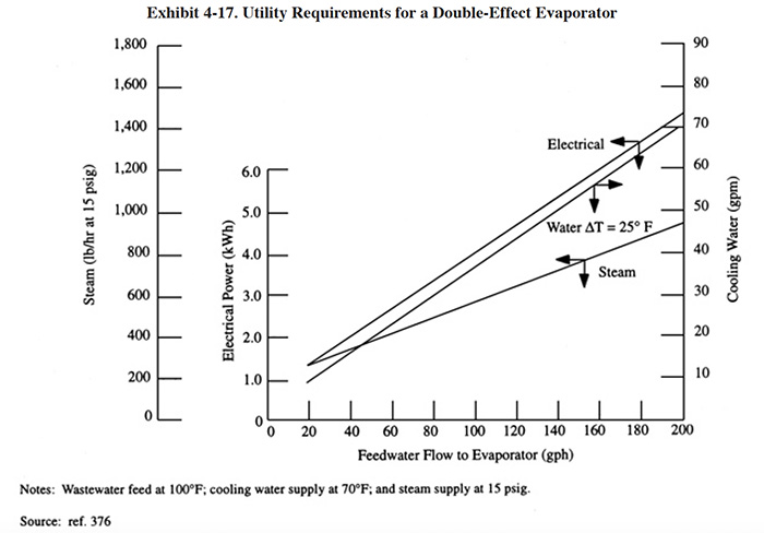 |
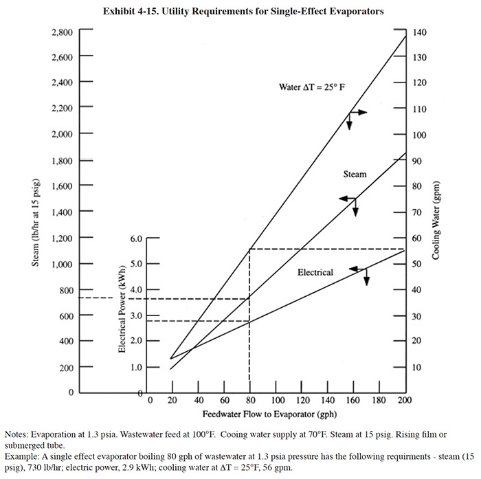
Exhibit 4-15 shows the utility requirements for single-effect evaporators as a function of liquid flow rates to the evaporator. The electrical demand is associated with power requirements of the vacuum pump, recirculation pump, and feed pump. As a rule, the cooling water rates are based on a temperature rise of 25°F (14°C) across the condenser (ref. 376). For example, from Exhibit 4-14, if the wastewater flow rate to the evaporator is 80 gal/hr (303 l/hr), the steam rate is 730 lb/hr (331 kg/hr) for 15 lb/in2 gauge (1,536 mm Hg absolute) steam. The electrical demand is 2.9 kWh and the cooling water rate is 56 gal/min (212 l/min). For atmospheric evaporators where no cooling water is used, the steam rate would be at least 20 percent higher (ref. 376).
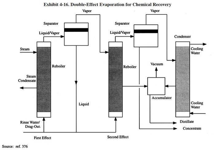
A general application of a double-effect evaporator, is shown in Exhibit 4-16. The basic principle is to use the heat given up by condensation in one effect to provide the reboiler heat for another effect. In the system shown in Exhibit 4-16, approximately 50 percent of the wastewater is concentrated in the first effect using steam. The vapor from the separator of the first effect enters the second-effect reboiler and condenses to provide the thermal energy required to reach the final concentration of the plating solution.
The steam and cooling water rates for the double-effect unit in Exhibit 4-17 are approximately 50 percent of those required for the single-effect unit.
Some platers using double-effect units achieve an additional benefit by recovering two different plating baths simultaneously. However, care should be taken in employing this arrangement however, because there is a possibility of cross-contaminating baths (ref. 376).
Multiple effect evaporation, when used in the plating industry, is most often applied to submerged tube evaporators, rinsing film and flash types (ref. 376). An alternative method for reusing the heat value contained in the vapor from the separator is to employ a mechanical compressor (see Section 4.4.2.9).
4.3.5 Costs
4.3.5.1 Capital Costs
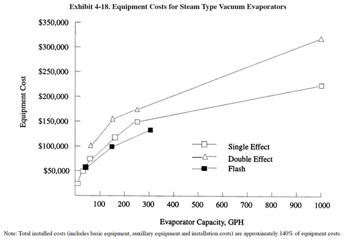
The basic equipment costs and installed costs for vacuum evaporators are indicated in Exhibits 4-18 and 4-19 for heat generated (steam) and electric types. Equipment costs will vary depending on the materials of construction; costs shown are for the basic materials offered by the manufacturer. Evaporators are currently marketed with a wide range of construction materials to resist the corrosiveness of various plating chemicals. The more popular materials include titanium, tantalum, borosilicate glass, stainless steel and carbon steel. Most evaporators are supplied as package units and only require the hook-up of utilities before start-up. However, some ancillary equipment is required (e.g., tanks), which are reflected in the installed costs. The installed cost estimate (140% of basic equipment cost) is based on Users Survey data.
 |
 |
Due to the capital intensive nature of this technology, it is prudent that the buyer make every effort to reduce the
flow rate of the feed stream by employing pollution prevention measures. Methods of flow reduction are discussed in
Section 3.
When selecting a vacuum evaporator, the plater should consider, in addition to costs, the following: (1)
availability, quantity and quality of steam, hot water or waste heat (i.e., if unavailable or insufficient, then
choose one of the electric units); (2) cooling water requirements; (3) electrical power requirements; (4) maximum
temperature that can be applied to the feed stream (i.e., concern for heat sensitive chemicals); (5) expected feed
rate; (6) required solids concentration of product (i.e., how concentrated must the plating solution be before it
can be returned to the bath); (7) anticipated use of distillate;(8) materials of construction (depends on both the
type and maximum concentration of chemicals); (9) controls (most units have microprocessor controls for automatic
operation and manual override); (10) auxiliary equipment requirements (e.g., bath maintenance technologies for
removal of contaminants that will be returned to the bath by the evaporator); and (11) O & M requirements (level
of expertise required and number of man-hours per year).
4.3.5.2 Operating Costs
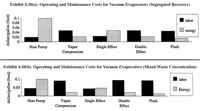
The primary operating costs for vacuum evaporators are labor, energy and cooling water. Energy and operating labor costs per gallon evaporated are shown in Exhibit 4-20. In this exhibit, a distinction is made between operating costs for segregated recovery and the concentration of mixed waste streams (e.g., end-of-pipe). Higher O&M costs can be expected for end-of-pipe applications because the solutions are evaporated to higher solids levels, which increases fouling and scaling.
4.3.6 Performance Experience
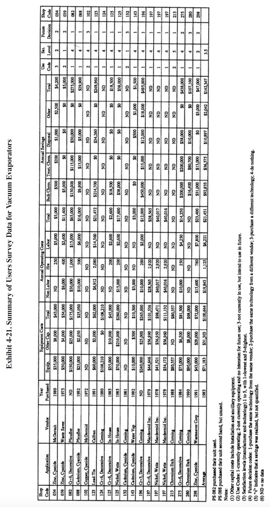
A partial summary of the user data relative to vacuum evaporation is presented in Exhibit 4-21. There are a number of observations that can be made from these data and other data contained in the database and literature:
- The average satisfaction level for chemical recov-ery applications is 3.5 (on a scale of 1 to 5, with 5 being most satisfactory), which higher than the average rating for all recovery technologies. Seventy-five percent of the shops using vacuum evaporation for chemical recovery indicated that this technology satisfied the need for which it was purchased. The following is a breakdown of the reasons why shops purchased this technology:
To meet of help meet effluent regulations: 14 To reduce plating chemical purchases: 12 To reduce the quantity of waste shipped off-site: 12 To reduce wastewater treatment costs: 11 To improve product quantity: 0 To close-loop a particular process: 1
- Vacuum evaporators were successful for most applications identified in the Users Survey except for zinc-cyanide plating solution recovery. The average annual savings from using vacuum evaporators exceeded the sum of the average capital cost plus the average annual operating cost. The most significant savings were derived from reductions of bath chemical and treatment chemical usage.
- The use of vacuum evaporation as a recovery technology generally did not impact production quality or the rate of production for the survey respondents. The following responses were provided:
Product Quality Production Rate Improved 1 1 No Change 13 13 Decreased 2 0
- PS 298 indicated that use of their evaporator decreases product quality because their distillate is contaminated and not adequate for good rinsing. PS 102 also indicated that their unit decreases product quality.
- The respondents indicated, that based on their experience with this technology and, if given the opportunity,
they would:
Purchase the same technology from the same vendor: 12 Purchase the same technology from a different vendor: 4 Purchase a different technology: 3 Do nothing: 0
- Two of the respondents indicated that their vacuum evaporation system was the cause of an effluent compliance excursion (PS 039 and PS 088). PS 280 did not respond to the question. All other respondents indicated that their vacuum evaporation system was not the cause of an effluent compliance excursion.
- Several respondents provided the following quantitative performance data:
- PS 082 indicated that the supplier stated capacity of their unit is 300 gph and that the actual capacity is 175 gph.
- PS 123 has an evaporation rate of only 6 gph. It is used to make head-room in their tin-lead plating tank so that recovery rinsing can be used. The feed to their unit (tin-lead plating solution), has a concentration of 16 to 18 oz/gal and the concentrated return has a concentration of 32 to 36 oz/gal.
- PS 088 indicated that the capacity of their unit is 60 gph and that they are able to operate their cadmium plating process on a closed-loop basis. Their dragout rate is 1.5 gph and they have a three stage counterflow rinse system feeding the evaporator. The cadmium bath is operated at 75°F and there is essentially no surface evaporation.
- PS 124 indicated that their unit has a capacity of 90 gph.
- PS 125 indicated that their unit has a capacity of 100 gph.
- PS 196 indicated that both the supplier stated capacities and actual capacities of their units (3) were 90, 75 and 50 gph.
- PS 213 indicated that both the supplier stated capacity and actual capacity of their unit was 75 gph.
- PS 298 indicated that their "unit does not meet levels stated in promotional" and that the "quality of distilled water is poor." The supplier stated capacity of their unit is 100 gph and the actual capacity is 70 to 80 gph.
- PS 132 indicated that their evaporator "never performed as sold." No details of their problems were provided.
- PS 034 expressed their feelings about their unit as follows: "Poor design, good technology."
4.3.7 Operational and Maintenance Experience
The following summarizes the respondent's O&M experiences and provides operating labor information relative to vacuum evaporators.
- The average number of annual man-hours spent for operating and maintaining a vacuum evaporation unit were: 657
hrs/yr. The skill requirement commonly needed for operating this technology is trained technician or a
wastewater treatment plant operator. The following is a breakdown of the responses for skill requirements:
Environmental Engineer: 1 Process/Chemical Engineer: 1 Chemist: 1 Consultant: 1 Plumber/Pipe Fitter: 4 Electrician: 4 Vendor: 1 Senior-Level Plater: 4 Junior Level Plater: 1 Wastewater Treatment Plant Operator: 8 Trained Technician: 9 Common Labor: 1 Other: 0
- The most frequent and significant operational and maintenance problems identified with vacuum evaporation include: (1) mechanical problems with pumps; (2) damage to components by aggressive plating chemicals; and (3) contamination build-up in the plating bath.
- Approximately 26% of the total number of vacuum evaporation units reported in the survey forms are no longer in use. On the average, these units were purchased 16 years ago. Of those units still in use, the average age is 6 years. The oldest working unit was 14 years old.
- PS 034 indicated that they have weekly problems with their pump and vacuum system.
They attribute the pump problems to improper design. PS 039 also indicated that they problems with the vacuum pump. On a second unit, PS 039 had problems with the eductors. They have abandoned use of both of these units.
- Although they have installed both ion exchange and electrolytic purification, PS 082 indicated that they have trouble keeping their chromium bath free of contaminants because of the closed-loop recovery process. PS 102 used their unit for 4 years and then abandoned its use because of plating bath (copper, cyanide) contamination. PS 125 is experiencing a build-up of sodium and chloride in their nickel bath.
- PS 088 reported that their cooling water was too warm in the summer to effectively condense the vapors and operate their system.
- PS 088, which employs a four stage counterflow rinse prior to evaporation, indicated that users of this technology should concentrate on reducing rinse water flow and the resultant feed to the evaporator.
- PS 124 indicated that they need to clean the condenser of their unit approximately twice per year.
- PS 124 indicated that the maximum feed concentration to their unit is 1 oz/gal CrO3 (presumably because higher concentrations will etch the glass of their Corning evaporation unit.) PS 196 reported some etching of their glass unit. PS 280, which operates a Corning unit with a fluoride bath, indicated that this application results in a shorter than average equipment life-span and higher maintenance costs. Their unit is three years old.
- PS 125 indicated that they must operate one of their units at <150°F because of nickel brightener considerations (nickel plating) and the other unit at ≤140°F due to fluoride considerations (decorative chromium plating).
- PS 196 indicated that they must operate their unit at >150°F to boil the chromium solution.
- PS 298 indicated that their distillate is some times contaminated beyond the limit for good rinsing. When this occurs, they recycle the distillate to the first rinse rather than the final rinse of their 3 stage counterflow rinse system. This results in a need to blow down rinse water to the treatment system.
4.3.8 Residuals Generation
Vacuum evaporators used for the recovery of plating chemicals create three streams: (1) the concentrate, which is reused in the plating bath; (2) the distillate, which is reused in the rinse system; and (3) cooling water, which is recycled using a cooling tower, reused as rinse water or discharged to the sewer. Cooling water requirements were previously described in Exhibit 4-14 and 4-17.
Only two respondents indicated that they generate any residual wastes other than the three streams mentioned. PS 143 indicated that they generate approximately 30 gal/mth of sludge, which they mix with their other F006 sludge and sent to off-site recycle. This sludge is generated from the treatment of the distillate (cyanide oxidation, precipitation, filter press and sludge dryer), which they do not send to the rinse tanks. PS 298 reported that carbonates collect at the bottom of the evaporation chamber forcing periodic removal. They remove approximately 100 lbs/mth of this material and treat it on-site.
4.4 ION EXCHANGE
4.4.1 Overview
Ion exchange is a technology that is very familiar to the plating industry. The five most common applications of this technology by the plating industry are: (1) treatment of raw water (e.g., city water) to produce high quality rinse water (includes both softening and deionization); (2) chemical recovery from rinse water; (3) treatment of plating baths to remove contaminants (e.g., tramp metals);(4) as a primary end-of-pipe treatment process; and (5) as a polishing end-of-pipe treatment process to comply with stringent effluent limitations. Chemical recovery applications of ion exchange are covered in this section. Bath maintenance and end-of-pipe treatment applications are covered in Sections 5 and 7, respectively. Raw water treatment is not covered by this project, although some respondents indicated in their survey responses that they use ion exchange for raw water treatment (e.g., PS 127, PS 196, PS 203).
Ion exchange is a chemical reaction wherein an ion from solution is exchanged for a similarly charged ion attached to an immobile solid particle (i.e., ion exchange resin). Ion exchange reactions are stoichiometric (i.e., predictable based on chemical relationships) and reversible. The resins are normally contained in vessels referred to as columns. Solutions are passed through the columns and the exchange occurs. Subsequently, when the capacity of the resins is reached, the ions of interest, which are attached to the resin, are removed during a regeneration step where a strong solution containing the ions originally attached to the resin is passed over the bed.
The strategy employed in using this technology is to exchange somewhat harmless ions (e.g., hydrogen and hydroxyl ions), located on the resin, for ions of interest in the solution (e.g., plating chemicals). In the most basic sense, ion exchange materials are classified as either cationic or anionic. Cation resins exchange hydrogen ions for positively charged ions such as nickel, copper and sodium. Anion resins exchange hydroxyl ions for negatively charged ions such as chromates, sulfates and cyanide.
Ion exchange resins are usually contained in vessels referred to as columns. The basic column consists of a resin bed which is retained in the column with inlet and outlet screens, and service and regeneration flow distributors. Piping and valves are required to direct flow and instrumentation is required to control regeneration timing. The systems are typically operated in cycles consisting of the following steps (ref. 39, 348):
- Service (exhaustion) - Water solution containing ions is passed through the ion exchange column or bed until the exchange sites are exhausted.
- Backwash - The bed is washed (generally with water) in the reverse direction of the service cycle in order to expand and resettle the resin bed.
- Regeneration - The exchanger is regenerated by passing a concentrated solution of the ion originally associated with it through the resin bed; usually a strong mineral acid or base.
- Rinse - Excess regenerant is removed from the exchanger; usually by passing water through it.
4.4.2 Development and Commercialization
Ion exchange is a versatile separation process with potential for broad application in the metal finishing industry. The ion exchange process has been commercially available for many years, but early use was primarily for water deionization or softening. Widespread interest in the process for metal finishing pollution prevention and control is a more recent application that has grown rapidly over the past 10 to 20 years.
Although the ion exchange process was first recognized in 1850, and defined as a reversible process in 1858, the first practical application of the process did not occur until 1905 when the inorganic sodium aluminosilicate cation exchanger was synthesized and used to soften water. In the early 1930's a cation material was developed from sulfonated coals, which extended the operable pH range of the process. In 1935, condensate polymers were first used as structural substrates for various functional groups, thereby creating both anion and cation exchange materials. The early anion product was not the strong base anion exchanger available today. Instead, it acted as an acid adsorbent capable of removing only free acids from the process stream. The cation and anion forms were used in series for the first time and deionization was accomplished; however it was limited in application. Strong base anion exchange materials were developed in the 1940's that extended the use of the process. In 1945 synthetic organic polymers were developed using styrene and divinylbenzene as the monomers. These were later prepared in bead form (earlier, only granular products were available). This gave rise to the modern "gel" type ion exchange materials. Improvements during the 1950's focused on reducing the fouling of resins by organic substances (ref. 383). One of the earliest applications of ion exchange to metal finishing mentioned in the literature was a hard chromium bath maintenance system operated by the Rock Island Arsenal in 1952 (ref. 368). The use of ion exchange as a pollution control and chemical recovery tool progressed steadily as pollution control regulations became more widespread and more stringent. As with many technologies, ion exchange use for pollution control in the metal finishing industry increased very rapidly in the late 1970's and early 1980's with the implementation of the Federal effluent guidelines. The most recent developments have focused on expanding the range of applications (e.g., cyanide plating and electroless plating baths) with new resins, equipment and techniques.
4.4.3 Applications and Restrictions
Ion exchange is used for a variety of purposes in the metal finishing shop, including: treatment of raw water; recovery of plating chemicals from rinse water; purification of plating solutions; wastewater treatment; and wastewater polishing. The following discussion of applications and restrictions focuses on use of this technology for chemical recovery from rinse water. The other applications, with the exception of raw water purification, are discussed in other interim reports.
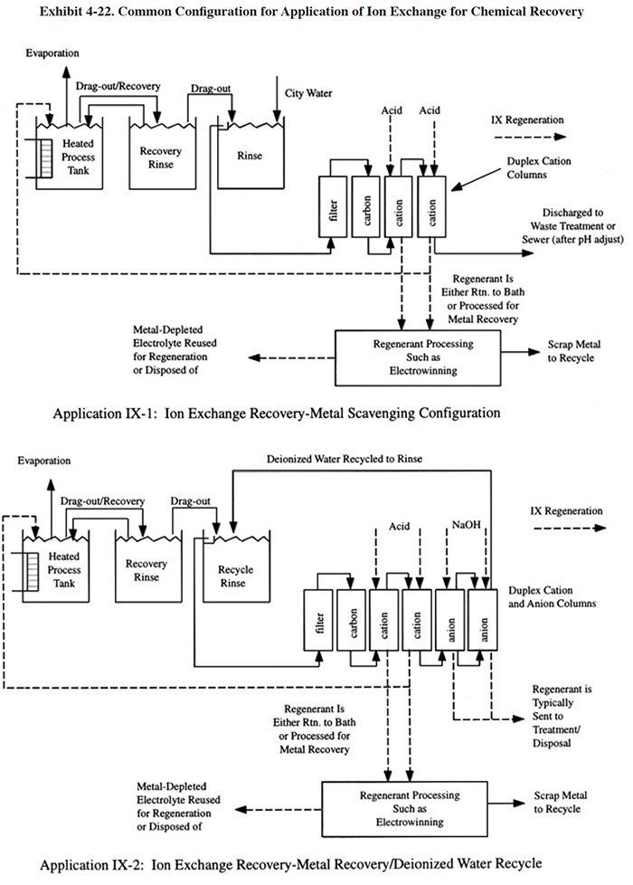
Ion exchange is a useful technology for recovering plating chemicals from dilute rinse waters. Two common configurations are shown in Exhibit 4-22, application IX-1 is referred to as metal scavenging. It uses only one type of ion exchange resin, either anion or cation, depending on the charge of metal or metal complex being recovered. Because this system does not have both cation and anion resins, the rinse water will not be fully "deionized" and cannot be reused as rinse water for common rinsing purposes. In AE-2, both anion and cation resins are employed and the rinse water can be recirculated in a closed loop. With both of these configurations, rinse water containing a dilute concentration of plating chemicals is passed through an anion and/or cation column (or dual columns of the same type) and the metals are removed from the rinse water and held by the ion exchange resin. When the capacity of the unit is reached, the resin is regenerated and the metals are concentrated into a manageable volume of solution. Depending on the chemical nature of the process, the regenerant (eluate) solution can be returned directly to the plating tank for reuse, further processed and returned, or the metals can be recovered by another technology such as electrowinning (see Section 4.5). The most common applications for these configurations of ion exchange are with the recovery of copper, nickel, and precious metals.
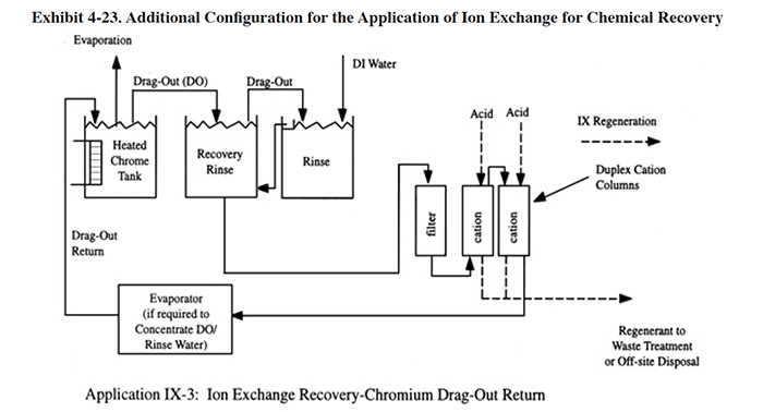
Application IX-3 (Exhibit 4-23) is a bath maintenance configuration that is only applicable to chromic acid solutions. The chromium bearing rinse water is passed through a cation column to remove trivalent chromium, and tramp metals such as iron, nickel and aluminum and it is then used as make-up for evaporation in the bath. This application prevents the build-up of contaminants in the bath, a process that is hastened by recovery rinsing. Since hexavalent chromium is an anion, it is not removed by the cation resin.
Dragout recovery tanks (see Section 3) are used with ion exchange systems whenever feasible. In operation, the dragout tanks return the bulk of the plating chemicals to the plating bath and an ion exchange column captures only the residual quantities of chemicals. The needed size of the ion exchange unit and its regeneration frequency are therefore reduced.
Some of the respondents to the Users Survey misapplied the ion exchange technology for chemical recovery. For example, PS 261, operates a Watts nickel plating line with a 140°F bath and a four stage counter flow rinse.
This shop feeds the ion exchange system from the first rinse, which is the most concentrated, and returns the treated water to the last rinse. Instead, this shop should utilize the configuration shown in Exhibit 4-22. Applica-tion IX-1. The use of a recovery rinse will greatly reduce the nickel load on the ion exchange columns.
As a recovery technology, ion exchange should be applied to dilute rinse waters. It is not applicable to concentrated dragout solutions or plating baths (although it can be used as a bath maintenance technology to remove tramp metals, see Section 5). A major limitation of this process is that many plating baths are more concentrated than the ion exchange regenerant. Therefore, it should not be used in a "bleed and feed" system, where spent bath is bled to the rinse water. The result in these cases is that the chemicals are diluted in the rinse water, collected by ion exchange, regenerated (using costly chemicals), and recovered in a lower concentration than they started (ref. 40).
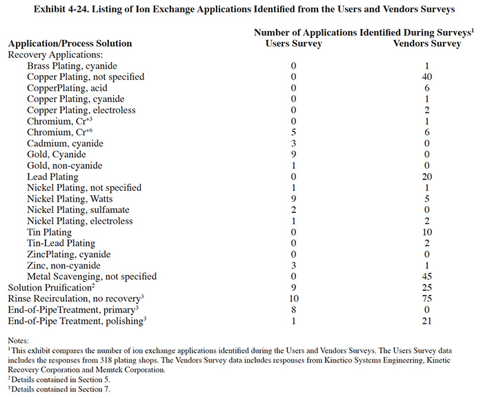
Ion exchange is applicable to a wide range of plating processes. Exhibit 4-24 shows the applications identified by the Users and Vendors Surveys.
Ion exchange is used much more frequently for metal recovery from non-cyanide solutions than for cyanide solutions (e.g., cadmium cyanide, copper cyanide, zinc cyanide), with the exception of gold cyanide. When applied to cyanide solutions, the task of recovery is more difficult due to the nature of the cyanide complex. As explained by Reinhard (ref. 342), when a cation followed by an anion column arrangement is used, the cyanide complex in the rinse water is decomposed into free metal cations and cyanide anions and these cations and anions are exchanged for H+ and OH- ions in the corresponding resin beds. When the cation resin bed becomes exhausted there is insufficient acidity left to decompose the cyanide complex which is an anion and it will be exchanged for an OH- ion in the anion resin bed. This presents a significant problem since the cyanide complex will accumulate in the anion resin and because of its high affinity to the resin matrix, regeneration will not remove it. If this occurs, the resin may require replacement. This problem is not a concern with gold cyanide applications because in most cases the resins are incinerated during the recovery process, rather than regenerated. Incineration of spent gold resin is an economically acceptable practice because of the relatively small quantity of resin used and its low cost in comparison to the gold contained on the resin.
Another operational problem with cyanide solutions can be caused by excessive free cyanide in the rinse water. If this condition exists, the free cyanide will remove the heavy metal from the cation resin and form a new metal-cyanide complex.
4.4.4 Technology/Equipment Description
The initial part of this section describes some of the more important design elements of ion exchange systems and the latter part presents a description of commercially available equipment.
4.4.4.1 Ion Exchange Resins and Columns
A wide range of ion exchange resins are manufactured, the choice of which depends mainly on the type of metal being recovered and the chemical composition and characteristics of the solution being treated. Properly matching the ion exchange resin and the process chemistry should result in efficient operation, quality byproducts and lower operating costs. Inappropriate selection of resin can result in total system failure.
Resins can be broadly classified as strong or weak acid cation exchangers or strong or weak base anion exchangers. Strong acid resins are so named because their chemical behavior is similar to that of a strong acid. The resins are highly ionized in both the acid and salt form. In a weak acid resin, the ionizable group is a carboxylic acid (COOH) rather than the sulfonic acid group (SO3H) used in strong acid resins. These resins behave similarly to weak organic acids that are weakly dissociated. Because weak acid resins have an affinity for hydrogen ions, they have a limited exchange capacity when used to treat solutions with a pH below 6.0 (ref. 39).
Like strong acid resins, strong base resins are highly ionized and can be used over the entire pH range. Weak base resins are like weak acid resins, in that the degree of ionization is strongly influenced by pH. Consequently, weak base resins exhibit minimum exchange capacity above a pH of 7.0 (ref. 39).
A major advantage of both weak acid and weak base resins is that they can be regenerated much more efficiently than the strong acid and strong base resins. The weakly ionized resins can be regenerated using slightly greater than the stoichiometric reagent requirements, whereas the strongly ionized resins require significantly more regenerant (ref. 39).
Many specialty resins, such as chelating resins, are also in commercial use. Chelating resins that exhibit a high selectivity for heavy metal cations over other cations in solution have been commonly used in metal finishing, especially in the past ten years. Because of their selectivity, they are especially useful for end-of-pipe polishing following hydroxide precipitation. Chelating resins are also used in recovery with electroless copper and electroless nickel plating solutions.
Generally, chelating resins cannot be used at low pH (<4) and a pH adjustment step is typically needed before the ion exchange process.
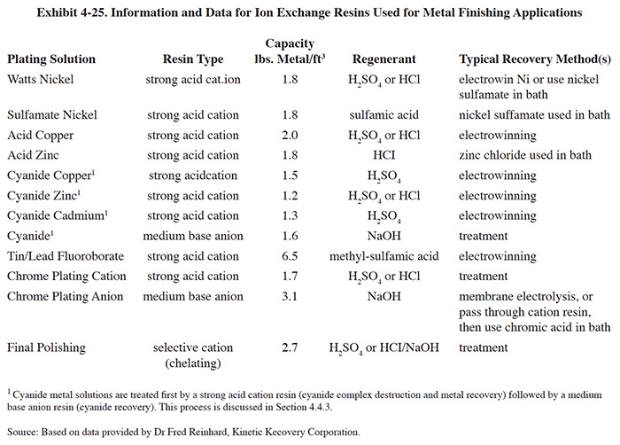
Exhibit 4-25 provides some general guidance on the types and capacities of resins used for common metal finishing
chemical recovery applications, the chemicals used for regeneration and the method of recovery.
Most industrial applications of ion exchange used fixed-bed column systems, the basic component of which is the ion
exchange column. The column must:
- Contain and support the ion exchange resin
- Uniformly distribute the service and regeneration flow through the resin bed
- Provide space to fluidize the resin during backwash
- Include the piping, valves, and instruments needed to regulate flow of feed, regenerant, and backwash solutions
After the feed solution is processed to the extent that the resin becomes exhausted and cannot accomplish any further ion exchange, the resin must be regenerated. Resin capacity is usually expressed in terms of equivalents per liter (eq/l) of resin. An equivalent is the molecular weight in grams of the compound divided by its electrical charge or valence. For example, a resin with an exchange capacity of 1 eq/l could remove 37.5 gram of divalent zinc (Zn+2, molecular weight of 65) from solution (ref. 39).
The hydraulic loading of resins will vary considerably from application to application, depending on: column design; type of resin employed; concentration of metal in solution; other chemical characteristics of the feed solution (e.g., pH); and the allowable concentration of metal in the column effluent. Typical hydraulic loadings range from 2 to 3 gpm of rinse water per cubic foot of resin.
4.4.4.2 Integrated vs Modular Designs
An integrated ion exchange system design is one in which the various components needed to perform the ion exchange recovery and regeneration functions are connected within the one unit. Such systems may also have attached electrowinning units and/or chemical treatment systems for processing the regenerant. The modular or point source design separates the ion exchange column from the regeneration and regenerant processing equipment. With the modular design, the columns are transported to a central station for regeneration (in some cases the modules are hard piped). The regeneration station can be either in the plating shop or at an off-site location (i.e., centralized waste treatment facility). The modular ion exchange strategy can reduce capital costs for small to medium-sized applications where low to moderate regeneration frequency is required. Also, the modular units are considerably smaller and therefore do not occupy as much production area floor space as integrated units (i.e., if the regeneration station is remotely located to a non-production area). However, operating costs are usually higher for modular systems due to the labor needed for transporting the modules and connecting them to the regeneration station (or for changing operating modes and valve positions for hard piped modular systems ) and initiating regeneration. Some commercial ion exchange modules have the appearance of large cans and are referred to as ion exchange canisters. With this type of unit, the canisters can be stacked upon one another to combine anion and cation types or to increase the resin bed volume. Standard column designs are also available.
4.4.4.3 Single vs Duplex Column Operation
Duplex column ion exchange systems are used in many chemical recovery operations, especially where a continuous feed flow is expected. Dual column configurations avoid downtime during regeneration. Two different duplex column arrangements are commonly used. In one arrangement, which is referred to as parallel/standby, the feed stream flows through either one column or the other, but never both. The off-line column is regenerated and then is held in reserve until the other column is ready for regeneration. This is a somewhat inefficient use of the two columns since column switching must take place before breakthrough occurs, which happens before the resin is completely loaded with ions of interest. In the second case, which is referred to as lead/lag, the two columns are placed in series flow. During operation, the majority of metal removal is accomplished in the first column (lead column) until it approaches capacity. The process can continue until the first column is essentially loaded to full capacity with ions of interest, since the second column (lag column) will remove the breakthrough of the first column. After breakthrough is reached, the first column is taken off-line for regeneration and then put back into service as the lag column. The roles of the two columns continue to be reversed following each regeneration. The switching of the columns, initiating of regeneration and other functions of modern ion exchange equipment is usually controlled by a microprocessor.
A special single column design that is widely used is referred to as reciprocating flow ion exchange (RFIE). A commercial application of this design is the Recoflo® (ref. 39, 349, 364, 365). The Recoflo® system is characterized by its short resin beds (6 to 24 in. as compared to 40 to 60 in. minimum for standard counterflow design) containing fine particle size resin beads. The Recoflo® process operates in a counterflow mode (see Section 4.4.1.4) with approximately a five minute cycle. During the cycle, the feed stream is fed for approximately 2.5 minutes, then regeneration occurs for approximately 2.5 minutes. The cycles are controlled by a microprocessor and are continuously repeated. The short cycle time, which is made possible by the short resin bed, emulates a continuous flow process.
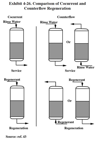
4.4.4.4 Counterflow vs Cocurrent Flow/Regeneration
One method of categorizing the operation of different ion exchange systems is by the direction of the service flow (e.g., rinse water) vs the direction of the regeneration flow. The two configurations that can be used are shown schematically in Exhibit 4-26. With cocurrent operation, the service flow and the regeneration cycle flow in the same direction and with countercurrent flow, they flow in opposite directions (as shown, service flow can be either downward or upward). Countercurrent flow is considered by most sources to be the more efficient method (e.g., ref. 42).
With cocurrent flow the hydrogen ions displace metal ions from the top to the lower portion of the bed. Complete removal of these ions can only be accomplished by the use of excessive levels of acid regenerant. With normal regenerant usage, there is a "heel" left at the exit end of the column (i.e., undisplaced metal ions). On the following service cycle, the desired exchange reaction occurs in the upper portion of the bed. However, as the hydrogen ion concentration increases toward the lower section of the bed, some reexchange with previously undisplaced metal ions leads to metal ion "leakage."
After regeneration of the counterflow system, the residual ions are in the top of the bed, with the bottom being fully converted to hydrogen. Thus, there are no residual metal ions present at the bottom of the bed to permit the leakage reaction to occur on the subsequent service cycle (ref. 43).
In addition to reduced ion leakage, counterflow regeneration can increase operating capacities, decrease the need for waste stream pH adjustment, and reduce water rinsing requirements (ref. 43).
4.4.4.5 Other Equipment/Design Considerations
In addition to the basic ion exchange column, auxiliary equipment is employed for various purposes, among which include: resin bed channeling and fouling prevention; pH adjustment of the feed stream; solution pump and flow control; need for regeneration identification; and regeneration cycle control.
Pretreatment of the feed stream is usually performed. Filtration is a basic requirement for nearly all ion exchange applications. If solids are permitted to enter the ion exchange bed, they will often create an uneven film on the top of the bed that acts as a plug. The solids will impede flow and cause channeling through the bed. Channeling of the feed solution will result in incomplete usage of the bed and inefficient processing (ref. 349). Most commonly, cartridge filtration is used for this purpose. Multimedia filters are sometimes used in high flow applications, where changing of the cartridge filters would be too time consuming (ref. 348). Other types of pretreatment include pH adjustment and carbon filtration. The adjustment of pH is used for certain applications where resin capacity can be enhanced by increasing or lowering the pH. Carbon filtration is used to remove certain organics such as oils that can become irreversibly sorbed by ion exchange resins and oxidants such as peroxide that can oxidize and ruin the resins (ref. 348).
The means for identifying the point at which regeneration should be initiated varies among commercially available equipment. The methods employed depend on the overall design of the system (e.g., a lead/lag unit may be able to tolerate some ion leakage from the first column whereas a single column may not), the tolerable leakage concentration, the variability of the feedstream, the ion(s) of concern, and the solution chemistry. Some equipment uses direct measurement methods to identify breakthrough. Examples of applicable methods and instruments include: conductivity meters, sometimes used in conjunction with pH meters; specific ion probes; and colorimetric analytical methods. A different strategy is to regenerate a column based on elapsed time or flow. These latter methods are applicable to feed streams with relatively constant parameters.
Other design features of ion exchange systems, such as controls, are discussed in Section 4.4.1.6.
4.4.4.6 Commercial Equipment
This subsection contains a description of commercially available ion exchange equipment that is manufactured and/or sold by vendor survey respondents. This is intended to provide the reader with information and data on a cross section of available equipment. Mention of trade names or commercial products is not intended to constitute endorsement for use.
Kinetico Engineered Systems, Inc. (Kinetico) manufactures various ion exchange equipment including that applicable to chemical recovery, bath maintenance, raw water treatment, and end-of-pipe polishing. Since 1980, they have sold more than 300 units. The Kinetico Complete Ion Exchange (CIX) series is applicable to metals recovery and water recycling with configurations similar to that shown in Exhibit 4-22 (applications IX-1 and IX-2). The CIX series are integrated packaged units with standard sizes ranging from 30 to 500 gpm. All units are dual column design for continuous operation (lead/lag configuration) with counterflow regeneration. Regeneration is initiated automatically by a patented control valve that monitors flow or by a manual override (push button). The control valve, which is non-electric, also directs the flow of solution for the regeneration cycle. Power for the valve comes from the flow and pressure of the water.
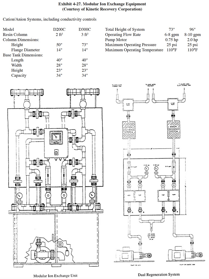
Kinetic Recovery Corporation offers modular ion exchange and regeneration systems for metals recovery and water recycling (see Exhibit 4-22, applications IX-1 and IX-2) as well as bath maintenance and end-of-pipe polishing. The modular ion exchange systems, which are dual column, are packaged with a cartridge filter system, flow meter, level sensor, feed pump, valve assembly, conductivity monitoring system and pump controls. The separate regeneration system (Exhibit 4-27) is capable of regenerating cation and anion exchange resins simultaneously. It consists of two chemical feed pumps, a valve assembly/control board with electrically actuated ball valves, flow meter and globe valve and a regeneration controller with a PLC and an operator interface. The valve assembly board allows the adjustment of the ion exchange into several modes of operation (parallel, series) and regeneration. With the operator interface unit, the regeneration mode can be selected and all operating conditions (mode, time elapsed, alarm condition) are displayed.
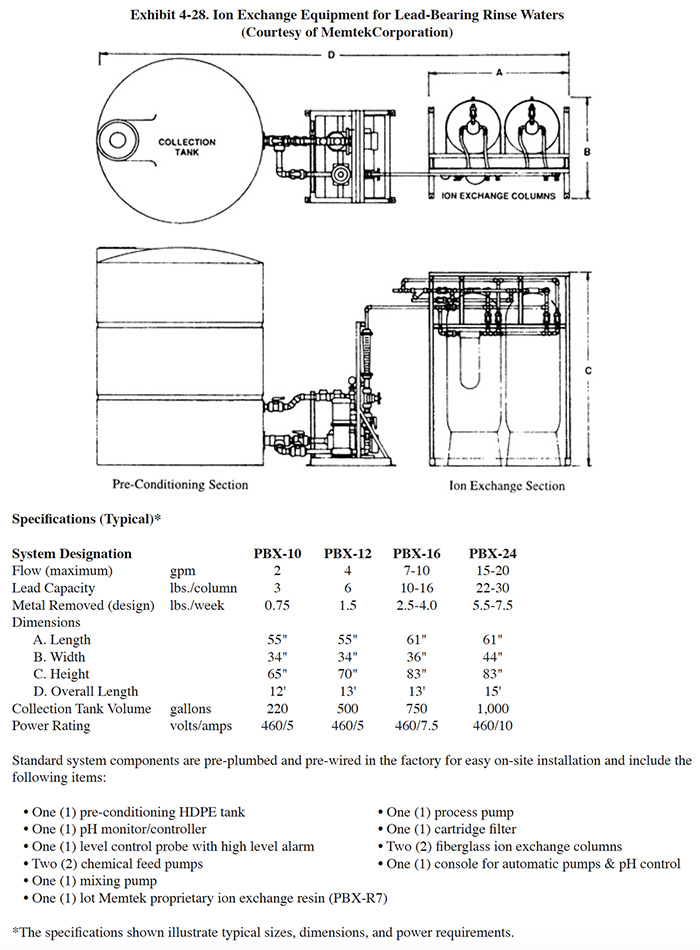
Memtek Corporation manufactures integrated ion exchange equipment for metal recovery and water recycling and end-of-pipe treatment. Their metals recovery/water recycle series (Rinse water Maintenance System or RMS™) is a dual column (lead/lag) packaged system with prefiltration, conductivity monitors and alarms, regenerant make-up tanks with level controls, and microprocessor controller. Memtek markets specific ion exchange systems for electroless copper and lead applications (see Exhibit 4-28). These two system include a preconditioning pH adjustment step.
Ionics International Ltd. (i3) offers both a semi-automatic integrated ion exchange system and a modular system with separate ion exchange and regeneration stations. Both the integrated and modular ion exchange systems are dual column (lead/lag) systems used for metals recovery and water recycle. The integrated systems typically include two anion and two cation columns containing approximately 6 ft3 of resin per column. Regeneration is manually initiated and automatically controlled. The modular systems are hard piped to the regeneration station rather than transported. The modular units typically permit a service flow rate of 10 gpm.
4.4.5 Costs
4.4.5.1 Capital Costs
Capital costs for modular and integrated ion exchange systems for metal recovery and water recycle (anion and cation columns) are presented in Exhibit 4-29. The modular ion exchange system costs are based on two responses to the Vendors Survey . The graphs show the costs for one and two modules of 2 ft3 and 3 ft3 capacities each. A single regeneration station is included in the cost for both the one and two module cases. Typically, one regeneration station can serve up to ten modules. Therefore, capital costs would be expected to increase in the step-wise manner shown in Exhibit 4-29 up to 20 ft3/30 ft3 resin capacities. The installed costs were estimated based on the projected costs for electrical and piping, including two components of electrical costs (service module and regeneration station) and three components of the piping costs (service module, regeneration module and service/regeneration module interface). The Vendor 1 system is hard piped to the regeneration station and the Vendor 2 system is transported (e.g., hand truck) to the regeneration station. Therefore, the vendor 2 installed cost includes only the first two piping components.
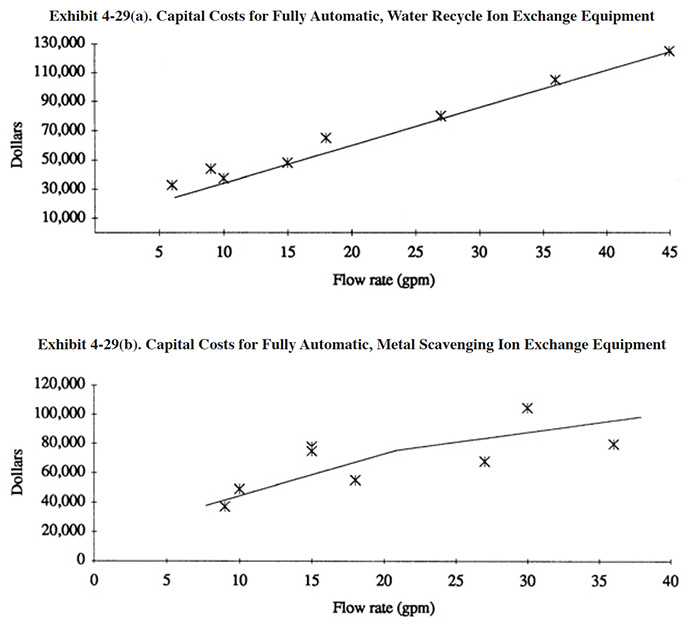
The integrated system capital costs include automated and semi-automated systems. The fundamental difference between the two types is that the regeneration cycle of the automated system is automatically initiated and the unit goes back into service automatically, whereas the semi-automatic system requires an operator to initiate regeneration and to put it back into service. Both systems operate automatically after regeneration or service is initiated. The installed cost for each system is the same, based on estimates for electrical and piping costs.
For small, manual applications, capacity is usually expressed in terms of resin volume, to which capital costs are directly related. Larger system capacities are more often expressed in terms of flow rate, but direct vendor-to-vendor pricing comparisons based only on capacity units such as gallons-per-minute can be quite misleading. Based only on flow rate specifications of four vendors, Exhibit 4-29 does not account for several cost factors including the amount of customization, the precise level of automation (which can vary considerably within the categories of "automatic" and "semi-automatic"), the type and quality of metering and monitoring instrumentation, and the general design strategies and criteria pursued by the manufacturer. These factors, in part, explain the wide range of prices quoted for similar flow rates.
Manual systems are often sized to provide an acceptable service period. Larger columns offer the benefit of fewer regenerations or replacements, less downtime and less labor expense. Automatic systems, on the other hand, are sized to handle the expected flow rate. While still a major design consideration, the service period has less impact on the user in terms of planning and labor. Thus, for highly automated systems, more frequent regenerations of smaller columns is a viable design strategy. An extreme example of this strategy is the reciprocation flow ion exchange, described in Section 4.4.4.3.
Water recycling systems are, in general, more expensive than metal-scavenging units. These systems require both anion and cation columns, which alone roughly doubles the regenerations required, and the cation resin must remove all cations, including non-regulated common cations such as calcium, sodium and potassium. In most cases, these factors make automation highly desirable or an outright requirement.
Installation expenses are site-specific but can be significant typically 5 to 40 percent or more of basic equipment costs). Shops currently employing trenches may require extensive plumbing to segregate the ion exchange stream from other wastewater. On the other hand, modular systems with off-site regeneration may incur no significant installation costs at all. In general, water-recycle systems that service several sources will require the largest installation outlay.
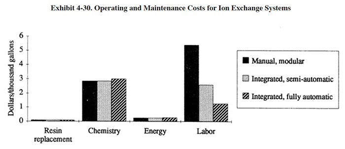
4.4.5.2 Operating Costs
Labor, regeneration chemistry, resin replacement, and energy are the major operating cost categories. Exhibit 4-30 presents operating costs for various operating modes of the ion exchange technology. This operating cost graph is based on a water-recycle application handling copper sulfate rinse water and is not necessarily representative of a wide range of applications.
Labor costs are significantly affected by the automation level of the system and automation capital costs are often
quickly returned. Undersized or misapplied equipment can greatly impact labor and other costs (see Section
4.4.7).
Resin life is usually measured in years, but can be shortened by misuse and improper application. Resin fouling,
mentioned by several respondents (see Section 4.4.7), is usually a result of a marginal application, misuse, or
insufficient upstream filtration or pre-treatment. Instrumentation designed to halt ion exchange system operation
when harmful levels of chemistries enter the feed stream can be cost-effective where spills and accidental dumps are
possible.
The operating costs estimates are based on the following assumptions:
Feed Characteristics (rinse water)/Resin Capacity
- Copper sulfate plating process generating rinse water containing 50 mg/l Cu++.
- Resin capacity of 38 eq. Cu++/ft3 (=12,900 gal between regenerations for 2 ft3 column).
- Assume two anion regenerations for each cation regeneration (=1.79 days between regenerations for 2 ft3 column).
Energy
- 1 hp-hr/300 gal
- $.10/kWh (= $0.25/1,000 gal)
Regeneration Chemicals
- Assume 4 bed volumes for cocurrent (Vendor 1-Modular) and 2 bed volumes for counterflow (all others).
- H2SO4 (Modular 1): 12 gal (conc.) @ $2/gal per 12,900 gal flow (= $1.9/1,000 gal)
- NaOH (Modular 1): 24 gal (conc.) @ $2/gal per 12,900 gal flow (= $3.8/1,000 gal)
Resin Replacement
- Assume 5 year life with 3% mechanical loss per year.
- Cation: $200/ft3 (= $0.03/1,000 gal)
- Anion: $400/ft3 (= $0.06/1,000 gal)
Labor
- $25.00/hr
- Modular 1: 1.0 hr/day (= $2.71/1,000 gal)
- Modular 2: 2.0 hr/day (requires transport) (= $5.43/1,000 gal)
- Semi-automatic: 1.0 hr/day (= $2.71/1,000 gal)
- Automatic: 0.5 hr/day (= $1.36/1,000 gal)
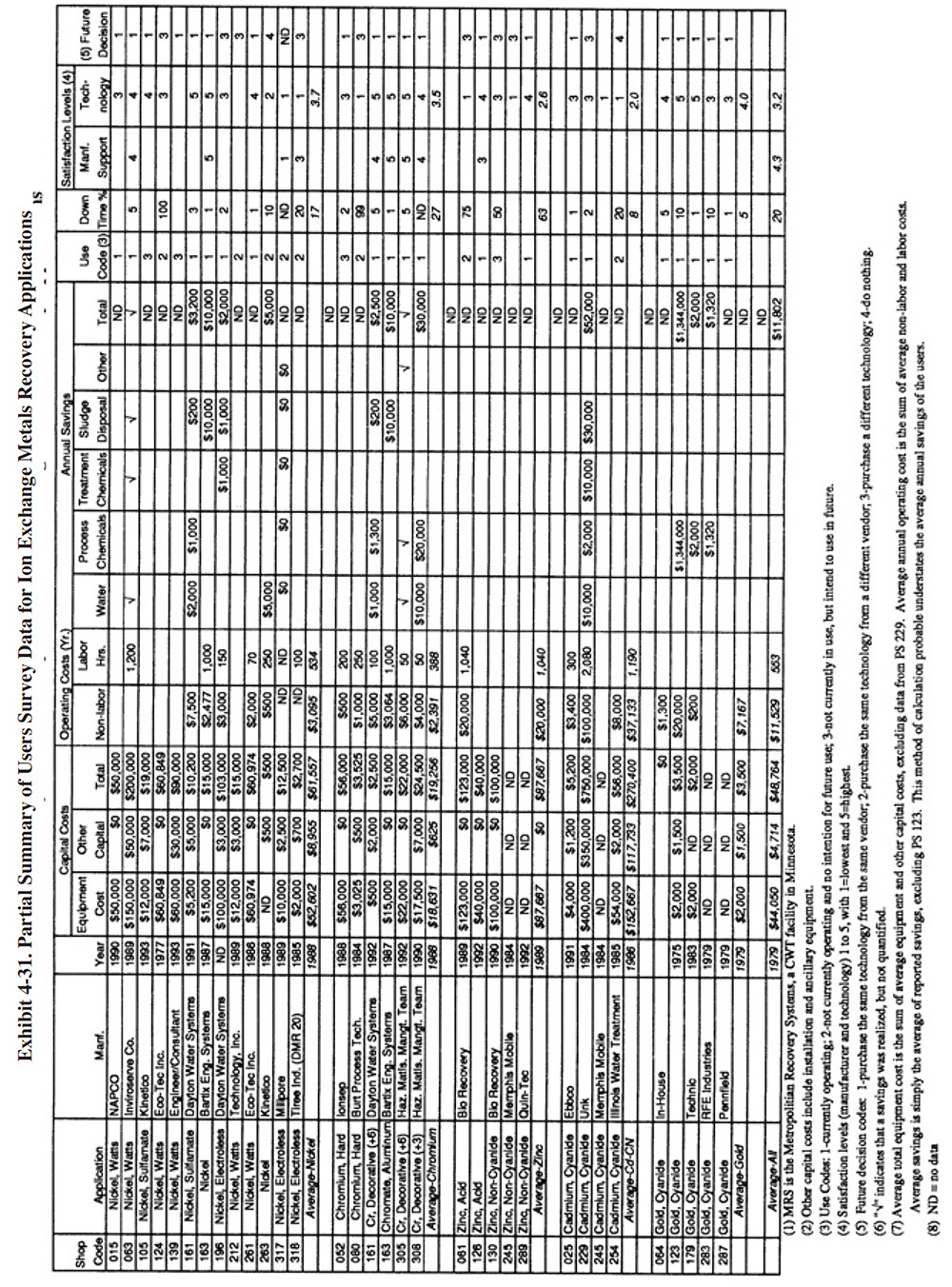
4.4.6 Performance Experience
A summary of the Users Survey data for ion exchange recovery applications is presented in Exhibit 4-31. Within this exhibit, the response data has been grouped by types of plating solution. These include: nickel, chromium, non-cyanide zinc, cadmium cyanide, and gold cyanide. A general discussion of the ion exchange data is presented) followed by specific information regarding each of the different types of applications.
The following information and data summarizes the performance experience of the survey respondents.
- The average satisfaction level for ion exchange recovery is 3.2 (on a scale of 1 to 5, with 5 being most satisfactory), which is lower than the average level rating for chemical recovery in general (weighted average for all chemical recovery applications is 3.4). Fifty-four percent of the shops indicated that this technology satisfied the need for which it was purchased and another 11% indicated that it partially satisfied their need. Thirty-five percent indicated that it did not satisfy the need for which it was purchased. The following is a breakdown of the reasons why shops purchased this technology (not all shops responded and some shops gave multiple reasons):
To meet or help meet effluent regulations: 21 To reduce plating chemical purchases:
(includes all four gold applications)8 To reduce the quantity of waste shipped off-site: 14 To reduce wastewater treatment costs: 13 To improve product quantity: 6 Other: 0
- The use of ion exchange generally did not impact production quality or the rate of production. The following responses were provided:
Product Quality Production Rate Improved 5 1 No Change 16 18 Decreased 3 4
- The majority of plating shops indicated, that based on their experience with this technology, if given the chance they would purchase the same type of equipment from the same vendor. The following is a breakdown of their responses:
Purchase the same technology from the same vendor: 18 Purchase the same technology from a different vendor: 0 Purchase a different technology: 8 Do nothing: 2
- The major savings from the operation of ion exchange for non-gold applications was due to reduced water use and reduced sludge generation. For gold applications, the major savings was due to the recovered gold.
4.4.6.1 Nickel Plating Performance Experience
Thirteen respondents to the User Survey provided detailed data regarding their experience applying ion exchange to nickel rinse waters. Two of these responses cover systems that were being installed at the time of the survey and therefore, no performance data are available from these shops (PS 105, PS 139). Three shops used the process for a short time period, but abandoned their efforts due to disappointing results (PS 212, PS 317, PS 318). None of the remaining eight shops currently operate ate the traditional recovery configurations (Exhibit 4-22), where the cation regenerant is subsequently processed by electrowinning to recover the nickel or nickel sulfate is returned to the bath. At one time, PS 124 recycled nickel sulfate regenerant directly to the bath. However, this shop discontinued use of the process due to "continuous and repeated" equipment failure. PS 015 purchased an electrowinning unit for nickel recovery, but the unit did not work and therefore, they selected to treat the regenerant instead. Also, one of the two new installations plans to operate with metal recovery (PS 139). Three shops use off-site recycling for regeneration of their columns (PS 161, PS 196 and PS 063) and another shop regenerates on-site and sends the regenerant to an offsite metals recycling firm (Inmetco) (PS 261).
Although no on-site recovery is presently practiced, the configurations used by the respondents involve the recycle of water. These applications have been included in this recovery section because they process a segregated nickel rinse water with ion exchange. As such, that they most likely experienced many of the same performance and O&M problems as recovery operations.
The following performance details were provided by survey respondents:
- The two most successful installations among survey respondents are PS 161 and PS 261. PS 161 sends their used ion exchange columns to off-site services for regeneration, most recently using Dayton Water Systems for regeneration of both nickel and chromium columns. This shop has used this form of off-site recycling since 1972. Originally, their equipment was purchased from Pollutronics and the columns were regenerated in Cleveland (company name not specified). They used Culligan's service in the late 1970's until 1991, when they switched to Dayton Water Systems "because of their recycling ability." After contacting Dayton Water Systems, it was learned that they do not currently provide a regeneration service for heavy metals, but may resume this service in the near future. The ion exchange columns used by PS 161 contain 3.2 ft3 of mixed (anion and cation) resin. During the past year, PS 161 sent 18 nickel columns and 8 chromium columns to Dayton Water Systems. The cost of the service was $336 per column for regeneration plus a $70 per month rental fee for the equipment (therefore, the total annual cost for most recent year is $6,888 for nickel and $3,528 for chromium). According to PS 161, Dayton Water Systems sent the regenerant to Inmetco for recovery of the metal (see Section 8 for information on off-site recycling).
- Only one of the shops indicated that an ion exchange unit applied to nickel plating was the cause of an effluent compliance excursion (PS 196). This shop stated: "Excursions happen when the mixed bed of resin is saturated with copper and nickel and will no longer polish the water." This shop uses an off-site service for regeneration and is charged by the number of columns used. Therefore, the shop may tend to load the resin beds to their maximum or beyond their breakthrough point.
- PS 261 reported a satisfaction level of 4 for ion exchange applied to nickel rinse waters. Their configuration is unusual in that the ion exchange unit is connected to the first rinse tank (i.e., most concentrated). Rinse water from the first rinse is pumped through the ion exchange column and is recycled to the last rinse (four-stage counterflow system). With this configuration, the ion exchange column receives the most concentrated rinse water. The normal configuration (see Exhibit 4-22) makes use of dragout recovery to reduce the chemical load on the ion exchange system and recycles the final rinse. Using their configuration, PS 261 probably experiences the need for frequent regeneration. Their regenerant is sent to Inmetco for off-site recycle.
- PS 317 and PS 318 applied ion exchange to rinse waters from electroless nickel plating. Both shops eventually abandoned their efforts to make the technology work. PS 317 described their use of the technology as a poor experience and indicated that their unit "required more water to restore the resin beads than water being processed." PS 318 indicated that the "process did not meet expectations or effluent guidelines."
4.4.6.2 Chromium Plating Performance Experience
Five respondents to the Users Survey provided some detailed data on their experience using ion exchange for chromium recovery. One of these shops uses an off-site regeneration/recycle service (PS 161) for regenerating columns applied to decorative chromium rinses (chromic acid, fluoride, barium carbonate). This shop also uses the off-site service for nickel recovery, details of which are provided in Section 4.4.6.1. Another respondent (PS 305) regenerates their unit on-site and sends the regenerant (sodium dichromate) to an off-site recycle company (Inmetco). One of the respondents recovers chromium from combined chromic acid anodizing and chromate conversion coating rinse waters and recycles the anion regenerant (dichromate) to the dichromate seal tank (PS 001). This system includes both anion and cation columns. The cation column removes contaminants such as aluminum and the anion column removes hexavalent chromium. Rinse water from the first rinse is filtered and passes through the columns and is returned to the final rinse. The cation column regenerant is treated and the anion column regenerant is transferred to the dichromate tank. Two of the four respondent's systems are not currently in use, but were previously used for chromium recovery from hard chrome plating rinse waters. One of these respondents intends to put their system back into use if the need arises (PS 052). Presently they have zero discharge, which is achieved through dragout recovery rinsing. Bath contaminants are removed using membrane electrolysis and a porous pot. The other shop tried the ion exchange process for a short time period in 1984 and does not intend to reuse it in the future (PS 080).
The following information and data summarize the performance experience of the five survey respondents.
- In one case, performance was hampered by opera-tional and maintenance problems. PS 080 indi-cated that: "Initial attempts to use ion exchange for removal of impurities from chromic acid rinse water failed. Resins became fouled and could not be regenerated and maintain plating production throughput requirements." It should be noted that this system was relatively inexpensive ($3,025) as compared to the other chromium recovery units. The respondent indicated that the supplier stated capacity was 200 gpd and that the actual capacity was 0 gpd. The respondent provided a diagram in the survey that seems to indicate they were processing rinse water from dragout tanks. This solution may have been overly concentrated with chromic acid for the apparently small ion exchange unit, causing almost immediate total loading of the resin. Also, their low capital expenditure may indicate that prefiltration was not included with the purchased ion exchange equipment.
- PS 001 indicated that the supplier stated capac-ity and the actual capacity of their ion exchange system was 6 gpm at a feed concentration of 100 mg/l CrO4. At this flow rate the system recovered 98% of the chromium.
- None of the shops indicated that an ion exchange unit applied to chromium recovery was the cause of an effluent compliance excursion.
4.4.6.3 Non-Cyanide Zinc Performance Expe-rience
Five respondents to the Users Survey provided data on their experience with ion exchange used with non-cyanide zinc plating. Only two of these respondents provided sufficient detail to be considered useful for this report (PS 061 and PS 130). Both of these systems were manufactured by the same company and were purchased just one month apart. One ion exchange system was applied to acid zinc and the other to alkaline zinc. As will be discussed, the performance of the two systems was reportedly very different. The more successful of the two systems (PS 130) is a combination ion exchange and electrowinning system, similar in configuration to that shown in Exhibit 4-22. The other shop (PS 061) used ion exchange as an end-of-pipe treatment for "zinc bearing rinses and selected bath dumps," with the ion exchange regenerant going to an evaporator for concentration and the concentrated solution being hauled to an offsite recycle firm. The ion exchange processed wastewater was pH adjusted and discharged to a city sewer. This shop does not have a conventional hydroxide precipitation system following the ion exchange process. Originally this shop planned to return the zinc chloride concentrate from the evaporator to the zinc plating tank. As discussed later in this section, this plan did not work.
The following information and data summarize the performance experience of the two survey respondents.
- One of the two shops providing detailed data on zinc applications indicated that their ion exchange unit was not the cause of an effluent compliance excursion (PS 130). The other shop indicated that their overall treatment system, which included zinc and chromium ion exchange, evaporation and pH adjustment, caused an effluent limitation excursion. Their treatment system was put into operation in December, 1989. On July 4, 1990, they received a cease and desist order from their control authority.
- The performance of the ion exchange system operated by PS 061 was hampered by operational and maintenance problems. These are discussed in Section 4.4.6.3.2. The supplier stated capacity of this application was 18 gpm and the actual capacity was 10 to 12 gpm.
- PS 061 originally planned to recover the zinc chloride regenerant by concentrating it with evaporation and then
reusing it in the zinc plating tank. This was not possible due to: (1) Chromium was present in the regenerant,
and to remove the chromium would have required redesigning the ion exchange system. (2) The amount of zinc
chloride generated by "false regenerations (a constant problem)" was much more volume than could be
used in the plating tank, even after evaporation. (3) The low pH of the regenerant kept destroying the heaters
in the evaporation unit and the steam from the system was so acidic that it corroded a hole in the shop roof.
This shop also tried to recover the zinc using electrowinning. They found that it was too difficult to maintain a
chemical balance during the process and that chlorine gas was liberated. Both problems made the process
ineffective and the electrowinning unit was never put into full operation.
- Although PS 130 gave their system a satisfaction level rating of 3, they indicated that its downtime due to O&M problems was 50%.
- Both of the shops indicated, that based on their experience with this technology, they would purchase a different technology if given the opportunity to repeat the process.
4.4.6.4 Cadmium Cyanide Performance Experience
Four respondents indicated that they have used ion exchange for chemical recovery with a cyanide plating solution other than gold cyanide. These four shops included four applications to cadmium cyanide rinse waters and one for zinc cyanide rinse waters (one shop did both).
The shop using both applications (PS 229) installed their equipment in stages during the early to mid-1980's and it was integrated with an HSA electrolytic recovery system. The shop provided insufficient details to draw any conclusions, however, they offered the following as a summary of their experience with the combined system: "Costs in 11 years far outweigh benefits. Would have been much more practical to install conventional precipitation technology."
The other three respondents also provided sketchy information for their applications. One of the units was a pilot system purchased in 1991 that is still being used in 1993 (PS 025). The response from that shop indicate that they are relatively satisfied with the system. PS 245 used a rented ion exchange column for cadmium recovery and found that the resins "loaded very quickly and did not appear to be the right application." They intend to use the equipment following conventional precipitation for water reuse. Since these two applications require different types of resins, it appears that this respondent has not received sufficient technical support to utilize this technology. PS 254 purchased ion exchange equipment in 1985 for cadmium recovery. They later eliminated the ion exchange process because it was recycling ferrocyanides to the plating bath.
The following information and data summarizes the performance experience of the survey respondents.
- The major savings from the operation of ionexchange for this application was the result ofwater use reduction, treatment chemical reductionand sludge volume reduction.
- PS 229 reported that the capacities of their ionexchange columns were 50 percent of the supplierstated capacity (2 lb/column vs 4 lb/column). Theyalso indicated that they were unable to reuse eithertheir zinc chloride or cadmium chloride regenerantdue to an excess volume problem in the platingtank (i.e., insufficient surface evaporation fromthe low temperature baths). They evaporate waterfrom the zinc chloride regenerant (500 gpy) andsend the concentrated solution to a landfill. Theyelectrowin cadmium from that regenerant (1,000gpy) and then send the metal-depleted regenerant to off-site disposal. A discussion of cyanideplating applications is presented in Section 4.4.3.Low cation capacity may be due to excess freecyanide. Methods for concentrating the solutionand making headroom in the plating tank using evaporation are discussed in Sections 4.2 and 4.3. Electrowinning of the cadmium regenerant is an acceptable method of recovery. The recovered metal can often be used as anode material. It is possible to increase the recovery rate by reusing the cation regenerant following electrowinning (see Exhibit 4-22). PS 229 also indicated that the fact that their equipment manufacturer went out of business within two years of installing their ion exchange equipment hindered the performance of their application.
- None of the shops completing the survey indicatedthat an ion exchange unit applied to cyanide plating rinse waters was the cause of an effluent compliance excursion.
4.4.6.5 Gold Cyanide Performance Experience
Five user survey respondents provided some detailed data on their experience with ion exchange used for gold recovery. All but one of these shops send their used resins to their gold solution supplier for credit toward bath chemicals. The other shop regenerates the resin on-site and uses electrowinning to recover the metal (PS 123). The following information and data summarizes the performance experience of the survey respondents.
- The average satisfaction level for ion exchangeapplied to gold cyanide is 4.0 (on a scale of 1 to5, with S being most satisfactory), which is higherthan the average level rating for ion exchangechemical recovery in general. Also, all of theshops indicated that this technology satisfied theneed for which it was purchased. In each case theneed was identified as reducing plating chemicalpurchases or other (i.e., reclaim gold). The rangeof savings from gold recovery for these shops was$1,320 (PS 283) to $134,400 (PS 123) per year.
- Only one of the shops provided any capacity data.PS 179 indicated that they experience an averageresin loading of 4 troy ounces per cubic foot ofresin. They typically use 1 ft3 of resin per year.
- In some cases, performance was hampered byoperational and maintenance problems. These arediscussed in Section 4.4.7.
4.4.7 Operational and Maintenance Experience
Of the 27 shops providing data, 17 (or 63%) were still operating their ion exchange equipment at the time of the survey. The average age of the operating systems was 7.0 years (only 4.2 years excluding gold plating applications). The average percentage of downtime experienced by the respondents was 20% (only 8.7% excluding PS 124, PS 080 and PS 061).
The following summarizes the respondents operating labor information. Details on O&M experiences are discussed for each type of application in Sections 4.4.7.1 through 4.4.7.5
- Fourteen shops provided operating labor data. For these shops, the average number of annual operating hours per ion exchange system were: 553 hrs/yr. The skill requirement commonly needed for operating this technology is a trained technician or a wastewater treatment plant operator. The following is a breakdown of the responses for skill requirements:
Environmental Engineer: 5 Process/Chemical Engineer: 5 Chemist: 4 Consultant: 3 Plumber/Pipe Fitter: 4 Electrician: 4 Vendor: 1 Senior-Level Plater: 6 Junior Level Plater: 4 Trained Technician: 14 Wastewater Treatment Plant Operator: 13 Common Labor: 3 Other: 0
4.4.7.1 Nickel Plating O&M Experiences
Reported O&M problems for nickel plating ion exchange applications relate to equipment failure and process chemistry concerns. Of the 11 shops providing data, six (or 63%) were still operating their ion exchange equipment at the time of the survey. The average age of the operating systems was 4.4 years. The average percentage of downtime experienced by the respondents was 17% (only 4% excluding PS 124).
The following O&M experiences were reported by respondents:
- PS 124 was the earliest installation (1977). Considering the cost ($6O,849 total installation cost), this was
apparently a major recycling project for the shop. The shop provided the following responses concerning the
equipment and the process: "Continuous and repeated failure of cheap valves used in design caused unit to
plug up". "Return of calcium sulfate to plating tank clogged pipes and anode bags."
- PS 212 reported that: "(The ion exchange system) was used for a short period of time. It never did the job
it was intended to do."
- PS 263 reported that their equipment, which they refer to as "prototype", "worked well, but
created plating problems." This was a 4 gpm unit that recycled rinse water from the final rinse of a
muti-stage counterflow rinse system. The shop believes that their plating problem was caused by the water in the
final rinse (i.e., that which is recycled to the ion exchange column) because it was too clean and resulted in
passivation of the nickel plated parts before chrome plating (i.e., the subsequent process).
- PS 261 was the only shop that reported that they had no significant O&M problems.
- PS 063 reported O&M problems with probe indicators and the balancing of chemicals.
4.4.7.2 Chromium Solutions O&M Experiences
Reported O&M problems for chromium ion exchange applications relate to resin fouling and equipment failure. Of the four respondents providing data for this application, two were still in operation at the time of the survey. The average age of operating systems was 3.5 years. The percentage of downtime experienced by the respondents was 27% (only 3% excluding PS 080).
The following summarizes the respondent's O&M experlences:
- PS 080 indicated that their ion exchange system failed due to resin fouling. A discussion of this shop's system is presented in Section 4.4.6.2.1.
- PS 052 indicated that their ion exchange regeneration process was very time consuming. They also indicated that
only dilute rinse waters can be effectively processed by the unit and that their rinse waters are occasionally
too concentrated for the unit.
- PS 001 indicated that their ion exchange system was also sensitive to the chromium concentration of the rinse
water (i.e., feed to the ion exchange unit) and that to prevent overloading of the resin they initially rinse
over the plating bath before using the rinse tanks.
- PS 305 indicated that they cannot process the contents of their dragout tank with ion exchange, without oxidizing the resin. (Note: The recovery of chemicals from concentrated solutions is not a good application for ion exchange. This technology is best applied to dilute solutions.)
4.4.7.3 Non-Cyanide Zinc Plating O&M Experiences
Reported O&M problems for non-cyanide zinc plating ion exchange applications relate to equipment failure and resin contamination with oil. Of the two respondents providing data for this application, none were still in operation at the time of the survey. One was purchased in December, 1989 (PS 061) and the other in January, 1990 (PS 130). PS 130 indicated that they intend to use their system in the future, although no specific plans were discussed in their survey form.
The following summarizes the respondents O&M experiences:
- PS 061 provided the following information that relates to O&M problems: "Never believe an engineer again! This technology should be never used to treat zinc wastewater from a job shop. Way too touchy-system, must be simple-discontinued July 4, 1990." "Pump failure, resin fouled, computer failure, float switch failure, heater failure, and on and on and on-" "Nothing worked for this project." This same shop offered the following regarding technical restrictions of the technology that they have encountered: "Chemical concentration & flow rates are critical! Failure of any one part can shut down the whole system without warning-[sic]"
- PS 130 indicated that the reason they are no longer using their zinc ion exchange system was a problem with oil in the rinse water feed to the unit that fouled the resin. They indicated that they plan on using the system in the future, after making changes to their cleaning process. This shop indicated the ion exchange system was not working 50% of the time as a result of the oil problem.
4.4.7.4 Cadmium Cyanide Plating O&M Experiences
Reported O&M problems for cadmium cyanide plating ion exchange applications relate to equipment failure, frequency of regeneration, excess regenerant production and bath contamination. Of the four shops providing data, two systems were operational at the time of the survey. The average age of the operating systems was 5.5 years. The average percentage of downtime reported by the respondents was 8%.
The following summarizes the respondents O&M experlences:
- PS 229 reported that their ion exchange units were overloaded due to high dragout rates and improper rinsing practices by their operators (discussed in Section 4.4.6.4.1). They also indicated that they felt their O&M problems were related to the manufacturer going out of business.
- PS 245 reported that their ion exchange columns loaded quickly and that the frequency of regeneration was very high.
- PS 254 eliminated their ion exchange process because it was returning ferrocyanides to the plating bath.
4.4.7.5 Gold Cyanide Plating O&M Experiences
Generally, the ion exchange units used for this purpose are small (< 0.5 ft3 of resin) and are free of complex regeneration and control systems. As a result, the operational and maintenance problems are minimal and the units that are purchased remain in use. In fact, all of the gold cyanide ion exchange installations identified in the Users Survey were in operation at the time of the survey. The average age of the units was 14 years. The only specific problem identified by a respondent was flow blockage caused by algae growth. The average percentage of downtime experienced by the respondents was 5%.
4.4.8 Residuals Generation
The primary residuals from ion exchange recovery processes are the regenerants (eluates) and backwash solutions. The regenerants are concentrated wastes and the backwash is dilute. Both solutions are either caustic or acidic, depending on the resin type and application. High metal bearing regenerates (typically cation resin) are: (1) sometimes reused directly in the bath; (2) further processed to recover the metal (e.g., electrowinning); (3) waste treated; or (4) sent to an off-site recovery facility. Low metal bearing regenerants (typically anion resin) and backwash solutions are typically treated on-site. Waste treatment processes generate sludge that is an EPA listed hazardous waste (F006).
The volume of regenerant produced will depend on the regeneration requirement (e.g., lbs of acid per ft3 of resin) and the concentration of acid used (typically 1 to 5%). The regeneration requirement will depend on the resin type, application (metal or complex being recovered) and the configuration (cocurrent vs counterflow). Typical volumes of regenerant are 20 to 50 gal/ft3 of resin. The volume of regenerant waste is sometimes reduced by reusing the last portion of the regenerant, which will be less contaminated with metal and contains free acid. Backwash volumes depend mostly on the equipment design and the application. Typically, backwashing generates 25 to 75 gal/ft3. The backwash is partly reused by some equipment vendors as make-up water for regenerant, in an effort to reduce the total waste volume generated. Because backwash contains only dilute concentrations of pollutants it is typically not a major concern and is treated on-site and discharged. However, for shops working toward zero discharge, the backwash volume could present a significant problem. Both backwash and regenerant can be processed by evaporation to reduce the volume requiring disposal.
However, this increases the capital and operating costs of the system. Also, evaporation of hazardous wastes is sometimes regulated as a RCRA technology and may require a permit to operate.
4.5 ELECTROWINNING
4.5.1 Overview
Electrowinning is one of the two most widely used methods of metal recovery in the plating industry, the other being atmospheric evaporation (Section 4.2). Of the 318 plating shops responding to the Users Survey, 61 (0r 19%) have employed this technology. Some shops have purchased or fabricated two or more units for differrent applications, resulting in a total number of 80 electrowinning units used by the 318 survey respondents.
Electrowinning is most frequently used to: (1) reduce the mass of inexpensive regulated metals (e.g., zinc, copper, lead) and cyanide being discharged to treatment and thereby reduce the quantity of treatment reagents used and the quantity of sludge generated and/or (2) recover expensive common metals (e.g., nickel and cadmium) or precious metals (e.g., silver and gold) for recovery/recycle and thereby reduce overall operating costs. In either case, electrowinning is most often applied for gross metal recovery from concentrated solutions such as dragout rinses or ion exchange regenerant. Used in this manner, it is not sufficient as a stand-alone technology to meet discharge standards. Reticulate cathode, high surface area (HSA) or high mass transfer (HMT) cathode designs also make this technology applicable to some dilute metal bearing solutions (e.g., overflow rinses). The reticulate cathode units have been proven to be effective in maintaining the metal concentration of recirculated rinses to less than 1 mg/l. The HSA units have been advertised as a method of compliance (ref. 98) and in the late 1970's and early 1980's attempts were made to use the electrowinning technology in this manner. However, none of Users Survey respondents are currently discharging an effluent from an HSA or HMT unit without further treatment for metals removal. Some non-continuous discharges of batch-treated solutions are found. However, for these cases, the volume of the discharge is insignificant compared to total wastewater flow.
The basic unit of the electrowinning technology is the electrolytic cell: two electrodes (anode and cathode) are placed in a solution containing ions, where there occurs a movement of ions toward the charged electrodes. Dissolved metals in the electrolyte are reduced and deposited on the cathode. The deposited metal is removed by mechanical (e.g. scraping) or chemical means and either reused as anode material or sent off-site for refining/reuse or disposal.
The types of cathodes used in electrowinning can be grouped into three categories. These include, in order of increasing surface area: (1) flat plate, (2) expanded metal, wire mesh or reticulate plate, and (3) porous or woven carbon and graphite types. The flat plate cathodes are used for applications of gross metal recovery from concentrated solutions (e.g., >1 g/l of metal). The expanded metal, wire mesh, or reticulate plate and the porous or woven types are used for recovering metals from solutions with lower metal concentrations, with the latter group effective in some cases in the low mg/l range. Reticulate cathodes, which permit flow-through of the electrolyte, have an effective surface area of approximately 10 times the face or apparent area of the cathode. Porous or woven cathodes have internal pores that also permit flow-through of the electrolyte and have a surface area up to 13,000 times greater than the apparent area.
There are several common terms used in describing the equipment and processes relative to electrowinning. The basic electrolytic cell is composed of two electrodes, one anode (positive charge) and one cathode (negative charge). The chemical reactions that take place at the anode are oxidations and the reactions at the cathode are reductions. The solution is referred to as an electrolyte. When a direct current (D.C.) is applied to the cell, the anions present in the electrolyte migrate toward the anode and the cations migrate toward the cathode. An important controlling factor in the process is the amount of current flowing through the cell. The level of current is measured in amperes per unit area of electrode (typically, amperes per square foot) and is referred to as the current density. Current density affects the nature of the electroplated deposit, the distribution of the deposit, the current efficiency, and to some extent whether a deposit forms at all. In electrowinning, the theoretical quantity of metal that is deposited onto the cathode is described by Faraday's Law. This law states that the amount of chemical change produced by an electric current is proportional to the quantity of electricity used (ref. 350). Some of the electric current is used for reactions other than metal deposit. Electroplaters refer to the ratio of desired chemical change (deposit) to the total chemical change as the current efficiency, usually expressed as a percentage of current applied.
As indicated previously, the current density has a substantial impact on the rate of metal deposit. It is desirable to operate electrowinning processes at the maximum current density where good deposition still takes place. The current density should, however, not exceed that which deposits metal faster than ions can diffuse through the electrolyte. When the thin film of electrolyte surrounding the cathode is depleted of metal ions, a condition referred to as concentration polarization occurs. This results in an adverse effect on the current efficiency as well as the quality of the deposit due to excessive hydrogen evolution at the cathode and oxygen evolution at the anode. The allowable or critical current density is determined by the concentration of metal ions in the electrolyte and the thickness of the film surrounding the cathode. Innovations in the design of electrowinning devices have generally focused on extending the operating range of the process by: (1) increasing the surface of the cathode (i.e., high surface area), or (2) reducing the thickness of the film using agitation or heating (ref. 349, 351).
For most applications, the primary use of electrowinning is the recovery of metal. However, when performed with an electrolyte containing cyanide, the process also oxidizes some of the cyanide at the anode (alternatively CN can be oxidized with hypochlorite ions which result from the electrochemical oxidation of chloride ion in a basic medium). Although the anodic reactions are given less consideration in most applications, they can play an important role in the economic viability of the process by reducing the treatment reagent requirements for end-of-pipe treatment. Anodic reactions including cyanide destruction and organic complexing agent destruction (e.g., treatment of an electroless copper bath) were examined in detail by Waiux and Nguyen (ref. 123).
4.5.2 Development and Commercialization
Electrowinning is presumed to be one of the earliest methods of metal recovery used in the plating industry, although no specific reference to its use prior to the 1960's was found (ref. 128). One of the reasons for its presumed early development and current widespread use is the fact that this process emulates the electroplating process. As such, it is readily accepted and understood by the plating industry. Further, for these same reasons, there are fewer system failures caused by misapplications or operational errors than with other recovery technologies such as ion exchange or membrane technologies. The electrowinning technology also has technical roots and contemporary applications in other industries, including electrorefining of copper, extraction of metallic aluminum from bauxite, and recovery of silver from photographic film manufacturing and developing operations.
Electrowinning can be performed using very simple equipment. As such, many plating shops have constructed units in-house. The effectiveness of these home-made units varies from shop to shop. Commercial units for plating applications are manufactured/sold by at least 40 companies (ref. 421). Many of these units, like the home-made models are also relatively simple in design. As discussed in Section 4.5.1, the efficiency of the electrowinning process is impacted by several electrochemical factors. Some commercial units, through the incorporation of more sophisticated design elements, minimize the impact of the electrochemical forces that reduce plating efficiency. Typically, these design elements are limited to the commercial units and are not found to any significant extent with the home-made versions.
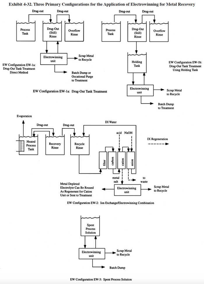
4.5.3 Applications and Restrictions
Exhibit 4-32 shows the three basic configurations in which electrowinning was successfully applied by the shops responding to the survey.
The most common configuration (EW-1) employs an electrowinning unit connected directly to a dragout tank. Alternatively, the solution from the dragout tank can be periodically transferred to a holding tank that is connected to the electrowinning unit. Either of these arrangements can be used with flat plate or reticulate cathode units. The reticulate cathode types will maintain the rinse system at a lower metal concentration (in some cases below 1 mg/l) but, because the cathodes are not reusable, the operating costs will be higher. The operation of the flat plate cathode types are more significantly affected by fluctuations in the metal concentration of the electrolyte. Therefore, if the plating operation causes sharp fluctuations in the dragout tank concentration, the user should consider the use of a side tank or a reticulate type of cathode. The HSA cathode units should be directly connected to the dragout tank. This will permit them to maintain a low steady state concentration of metal in the dragout tank.
Electrowinning removes metal from the dragout solution, but does not remove all dissolved solids. For this reason, the dragout solution must be occasionally discarded or purged to prevent the build-up of dissolved solids (e.g., acid). When this occurs, any residual metal in the dragout solution will be lost.
The metal recovery efficiency (i.e., the percentage of metal recovered from dragout) of the first configuration depends on two key factors: (1) the average concentration of metal in the dragout tank and (2) the mass of metal in the purge. The concentration of metal in the dragout tank is important because it determines the mass of metal that will be carried over by dragout to the next rinse, which is treated. This factor points out the weakness of the flat plate cathode types. These units operate efficiently only when the metal concentration is high (usually 1 to 5 g/l of metal). Therefore, the dragout tank must be operated until this level is achieved, which in turn increases the loss of metal to the free running rinse. The higher surface area of the reticulate and HSA units allow the user to operate the dragout tank at a lower metal concentration and therefore reduce metal losses. Further, these types of electrowinning units generate a purge with a lower metal concentration.
The second configuration (EW-2) is a combination of ion exchange and electrowinning. This configuration potentially has a much higher metal recovery efficiency than the first configuration. It addresses both of the factors that impact metal recovery efficiency. The ion exchange unit maintains a low metal concentration in the final rinse, thereby almost eliminating dragout losses. The ion exchange unit concentrates the metal into a regenerant stream and the electrowinning unit removes the metal. Residual metal in the regenerant is of less concern than the first configuration since it can be reconcentrated by the ion exchange unit. For the same reason, a flat plate cathode will suffice for this second configuration.
In some cases, the reticulate cathode units can be substituted for the second type of configuration. When such a unit maintains the dragout rinse in the low mg/l range, the metal recovery efficiency of the process would approach that of the ion exchange/electrowinning combination. Some recent operating data for a copper recovery application using this configuration are presented in Section 4.5.4.3.
The third configuration shows the recovery of metal from a spent process solution. Either the flat plate or reticulate cathode type of unit can be used in this configuration. The reticulate cathode type will provide greater metal recovery efficiency because it can lower the metal concentration of the spent bath below that of the flat plate. Because the reticulate cathodes are not reusable, its higher recovery efficiency comes at an increased operating cost.
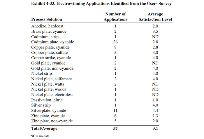
Electrowinning is applied to a wide variety of chemical solutions in the electroplating industry. The literature indicates that the metals that are most commonly recovered by electrolytic treatment are gold, silver, copper, cadmium, and zinc. The metal recovery applications identified from the Users Survey are shown in Exhibit 4-33. This exhibit indicates the number of survey respondents that applied electrowinning to each of the processes and the average satisfaction level of the technology for that application, based on a scale of 1 to 5 (1 equals the lowest satisfaction level and 5 equals the highest).
For practical purposes, the degree to which a metal can be recovered by electrowinning can be determined by its position in the Electromotive Series (see Exhibit 4-34). Metals that have more positive standard electrode potentials plate more easily than the ones with less positive potentials. As an illustration, the more noble metals, such as silver and gold, can be removed from solution to less than 1 mg/l using flat plate cathodes whereas with copper and tin, a concentration in the range of 0.5 to 1 g/l or more is required for a homogeneous metal deposit. Equations for accurately estimating the potential for a given application were presented by Brown (ref. 349) and Bailey and Chan (ref. 128).
It is interesting to compare the satisfaction levels in Exhibit 4-33 to the position of the metal in the electromotive series. The satisfaction levels for silver, copper, cadmium and zinc cyanide plating (the most common applications of the respondents) fall into nearly the exact order as the metal's position in the electromotive series.
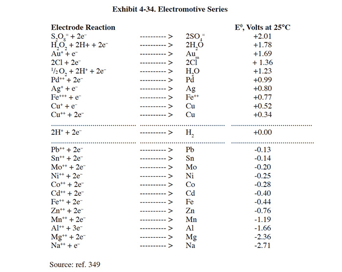
Although copper, cadmium and zinc have a lower position in the electromotive series than precious metals and they received only moderate to low satisfaction levels from survey respondents, this is not to say that these applications cannot be successfully performed. With the application of proper engineering and good equipment selection these electrowinning applications can be highly successful, as indicated by some of the respondents. For additional data, Exhibit 4-35 groups potential electrowinning applications based on their frequency of use and success in industry and the general difficulty of the application. These rankings are based on input from electrowinning vendors and information from the literature. Included in this exhibit are a much broader range of metals than those identified in the Users Survey.
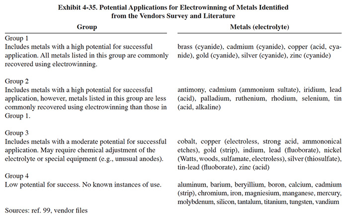
Although there are limitations for electrowinning nearly every metal, chromium is the only commonly electroplated metal that is not recoverable using electrowinning. Nickel recovery is possible, but it requires close control of pH and therefore is less frequently performed than, for example, cadmium or copper. Also, Altmayer suggests that nickel recovery is hampered by the absence of inexpensive suitable inert anodes that do not give off chlorine gas and disintegrate (ref. 482).
Solutions such as electroless plating solutions containing chelated metals, reducing agents and stabilizers are more difficult for the direct application of electrolytic recovery. However, there was one survey respondent that indicated they were successfully electrowinning nickel from a spent electroless solution (PS 188). Another shop (PS 164) is in the process of starting up a unit for the same purpose. One vendor (ref. 349) indicated that these baths can be processed by electrowinning after undergoing pretreatment (e.g., selective ion exchange) to break the metal-chelate bond. Another reference suggests that reducing and oxidizing agents can be combined to neutralize their effects; e.g., a printed circuit board shop can mix spent micro-etch and electroless copper baths and with proper pH adjustment create a solution that can be treated by electrowinning (ref. I3 file). Another reference indicates that electroless copper can be processed using electrowinning, but that anode life will be short (ref. 99).
Fluoborate solutions (e.g., tin, tin-lead) are not commonly treated using electrowinning due to their attack upon anode materials including iridium oxide coated titanium and niobium. However, one source (ref. 287) indicates that titania ceramic anodes coated with iridium can provide a successful application. This material and its application have been recently commercialized (ref. Kinetico file).
Certain corrosive solutions (e.g., certain etchants) may also pose problems for electrowinning because metal that is plated on the cathode may be etched off as quickly as it is plated (ref. 348). One reference suggests that increasing the current density will partially overcome the etching action of ammonomical etches when electrowinning copper from these solutions, but that complete removal is difficult to achieve (ref. 99).
CLICK HERE ... Section 4 is Continued