
Hard Chrome Plating Training Course
Appendix 9. Tracking Down Voltage Drops
Tracking Down Voltage Drops
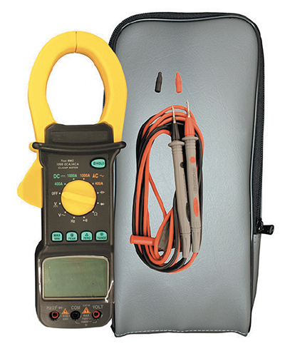
Exhibit A9-1. Digital handheld multimeter with clamp for current measurement.
A Voltage drop is the reduction in voltage in an electrical circuit between the source and load. With plating, voltage drops occur in the busing between the rectifier and the parts being plated. This is caused by the resistance in the bus and rack systems. There will always be some voltage drop, but in a well designed and maintained system the drop will be so small that it can be ignored. However, in other cases, voltage drops can impact plating rates, increase energy use, and cause bus bars to overheat, presenting a safety issue.
In this discussion, we will show you how to locate voltage drops and eliminate them.
Multimeter
A digital handheld multimeter, like the one shown in Exhibit A9-1 is all you need to check for and locate voltage drops. A decent device, such as this one, will cost under $200. It can be used to check both voltage and amperage. Every chrome shop should have at least two of these units. You need a minimum of two units, so that in the event that you get odd results from one unit, the second unit can be used to verify your result, or to indicate that you have a maintenance issue with your meter.
When using this device to measure voltage, connect the red (positive) and black (negative) cables/probes per the unit's instructions and set the mode to the correct DC voltage range (e.g., 0 to 6V).
Locating Voltage Drops
Check for voltage drops when parts are being plated in the tank. Voltage drops will be more apparent when the rectifier is under higher load.
When checking for voltage drops, start at the rectifier. Check the reading on the rectifier control panel and record this value. Then at the back or side of the rectifier, hold the multimeter black probe on the cathode (+) stub and the red cable on the anode (-) stub. Then read the meter and record this result.
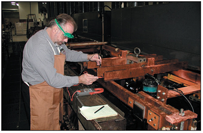
Exhibit A9-2. Checking voltage.
Now, follow the route of the rectifier busing. After each junction point, where bussing connections occur, check and record the voltage. Repeat this procedure for all connections, including the rectifier bussing and tank bus bars (Exhibit A9-2).
Then, check the voltage on the rack, at the lowest point you can, before it goes under the solution.
When taking these measurements, be careful not to touch connections or cables that may be overheating. A poor connection can cause a second degree burn in a matter of seconds.
After completing your voltage survey, create a table and evaluate the results.
Your measurement at the rectifier stubs should be the same as or very close to the rectifier control reading. If it is not, then either the rectifier meter is inaccurate or the hand held unit is inaccurate since there should be nearly zero voltage drop at this point.
Then, look at the other readings. A drop of 0.1 to 0.2 volts is not uncommon between the rectifier and the rack. When the drop is much more than 0.2 volts, then you should consider some maintenance or changes.
Reducing Voltage Drops
In most cases, the most noticeable voltage drop is caused by a poor connection between the rack or anode hook and tank bus bar. Most shops rely on the weight of the rack (or anodes) to provide a solid connection with the tank bussing.
That's acceptable as long as the connection is a good one. The primary potential problems include insufficient surface area for the connection and dirty connections. These connections often cause noticeable heating of the bussing or racks.
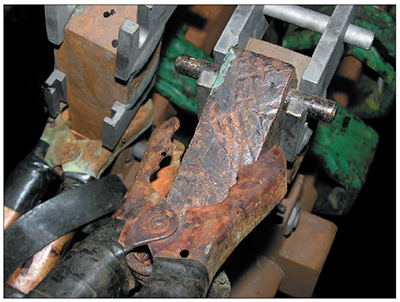
Exhibit A9-3. It is difficult to make good contact with jumper cables. They should only be used in low amperage situations.
When the problem is a poor connection, you need to perform some maintenance. Here are the basics:
- Replace undersized cables or busing with adequate equipment (1.0 to 1.2 in2 of copper per 1,000 amps)
- Avoid use of "jumper cables" (Exhibit A9-3) on larger parts
- Repair or replace connections that show a voltage drop of more than 0.2 V.
- Clean rack hooks and bus bars on a daily basis.
- Consider use of C-clamps to better secure racks to bus bars.
Rectifier bus joints and rectifier/tank connections are also a potential source of voltage drops. Generally, these connections are more permanent than tank rack/anode connections and do not require much, if any maintenance. However, if your voltage survey shows that a connection has a drop of more than 0.2 V, it should be taken apart, cleaned and repaired. One common problem with theses connections is that they are often not made correctly in the first place. Consult an electroplating handbook for instructions on how to construct bussing.