Hard Chrome Plating Training Course
Section 5—Troubleshooting
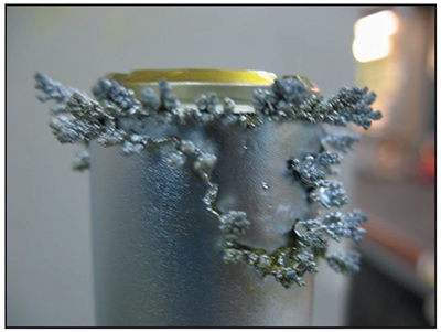
Exhibit 5-1. Stuff happens. Use this section of the course to reduce mistakes.
Okay, you plated a part and it looks bad, maybe roughness or pits. Or perhaps the deposit looked pretty good, but the grinder returned it to the plating shop because it didn't clean up (i.e., insufficient chrome), or it peeled off during grinding. Do you just give it another try, or do you totally change your approach to plating the part?
Generally, if you reuse the exact same procedures, equipment, and settings the problem will persist.
However, if you make a change, you may either solve the problem or begin to eliminate possible sources of error.
But, where should you start?
Hard chrome plating rejects are usually caused by one of seven system elements; these are listed below in descending
order, starting with the most likely cause.
- Plater error (not concentrating or deviating from established procedures)
- Electrical connections (bad connections)
- plating solution (bath chemistry is off, temperature is inaccurate)
- Grinder error (preplate and/or post-plate)
- Power source (rectifier and controls)
- Racks/fixtures (undersized or inappropriate)
- Work piece (part being plated may have unexpected metallurgical properties such as induction hardening)
The list and ordering of these sources of error is based on input from experienced platers. However, the order also makes sense from a practical standpoint. For example, let's compare a plater and a rectifier. A plater must perform many different tasks to plate a part correctly, and it is easy for him or her to vary their procedures slightly from part to part. But a rectifier simply provides direct current and will usually do that the same way each time it is put into service. Although rectifiers can break down, the chance of that happening is much less likely than the chance that a plater is going to make a mistake.
When you are troubleshooting, here are some logical methods that you can employ to help you zero in on the cause of defects:
- Try replating the part using the same procedures and equipment. However, this time pay particularly close attention to all details. For example, check to make sure that the cables and connections are not overheating during plating, and make corrections if necessary. If you discover the problem during replating, then the crisis is over. However, if no obvious glitches were found and the part plates satisfactorily, then the original problem was most likely (in descending order) #1, #2 or #4.
- If the defect remains after replating in the same tank, and another plating tank is available in-house, try plating the same part again in the other tank. If the part plates satisfactorily, then the problem is likely to be (in descending order) #3 or #5.
- If the part develops the same defect when plated in a different tank, then the problem is most likely (in descending order) #1, #4, #6 or #7.
Keep in mind that this procedure does not always solve the problem the first time. Some problems are seemingly illogical. That's usually the result of more than one element causing the problem. In such cases, you may correctly change one variable without solving the problem. However, using logic with various test sequences will usually track down the problem. Think in terms of the most likely causes first, and eliminate them through testing. Change one element at a time and see if you solve the problem. If you change multiple variables between tests, the problem may get worse, or if the problem is resolved, then you may never know the real cause of the problem.
To assist with your troubleshooting, this section contains explanations of the most common hard chrome plating problems, including descriptions, causes and cures. For quick reference, the information presented here is also summarized in Appendix 7.
Poor Chrome Appearance
In nearly all cases, a bright chromium deposit is the most desirable hard chrome plating result. Bright deposits have been proven to be harder deposits and they provide the greatest wear resistance, two key attributes of hard chrome. There may be problems if the coating:
- appears milky or hazy
- appears dull or frosty
- contains burnt deposits
Potential causes of poor chrome appearance are discussed in the following paragraphs.
Bright Range
This topic was discussed in Section 4, but due to its importance it is repeated here.
Although there are a number of potential causes for poor chrome appearance, the most common is a mismatch of current density and bath temperature:
- Current density is the amount of current being applied to the part divided by the surface area being plated. If you are plating a 100 in2 surface with a rectifier setting of 400 amps, then the current density is 4.0 amps per square inch (APSI).
- The bath temperature is usually held constant by a heating and cooling system connected to a controller that can be set at different temperatures.
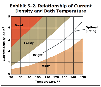
The relationship of current density to temperature is shown in Exhibit 5-2. In this graph you can see that bright chrome deposits can be attained at various current density and temperature settings. To be safe, it is best to operate in the center of the bright range, which is shown by the optimal plating line. Operating out of the bright range is the most common cause of poor chrome appearance.
Here's another way you may make use of Exhibit 5-2. Let's say that you get a really large part into your shop for plating; a piston with 2,500 square inches of surface area. The problem is that your largest rectifier has a maximum output of only 5,000 amps. Therefore, the highest current density you can plate this particular part is 2.0 APSI (5,000 amps/2,500 in2). If you plated the piston at 2.0 APSI in a bath with a temperature of 135 oF, you would most likely end up with a milky deposit. However, if you lower the bath temperature to 110oF, you will be right in the middle of the bright range. The plating rate will be very slow, but at least you will end up with a good deposit.
The values shown in Exhibit 5-2 are for standard single catalyst chrome baths containing 33 to 53 oz/gal chromic acid. For other bath formulations, consult your chemical supplier. They should be able to provide you with a similar graph.
Milky Deposit
Sometimes electrodeposited chromium will look milky, hazy, cloudy, streaked or banded. In addition to the current density-bath temperature issue already discussed, deposits exhibiting these problems could be the result of chloride or tramp metal* contamination of the plating bath. (*The most common tramp metals in a chrome bath include iron, copper, and aluminum. See Section 6 for a discussion of tramp metals.)
If parts plating from a given tank regularly have milky deposits, the bath should be tested for chlorides and tramp metals:
- Analyze the bath for chlorides (Cl–). The concentration should be kept below 25 mg/L Cl– and preferably near 0 mg/L Cl–. Dummy the bath or use a porous pot to reduce the chloride concentration. Chloride can also be removed by precipitation using silver oxide. Employ preventative measures to minimize future chloride buildup (e.g., use deionized water for bath evaporation make-up).
- Analyze the plating bath for iron, copper and other suspected tramp metals. The combined concentration should not exceed 7.5 g/L (1 oz/gal). Remove the tramp metal with ion exchange or other suitable technology or, less preferably, decant some of the chrome bath and make up the volume removed with fresh solution. Prevent future tramp metal contamination of the bath (e.g., use a dedicated etch tank, retrieve fallen fixtures from bath).
Frosty and Burnt Deposits
A common cause of frosty and burnt deposits is a mismatch of current density and bath temperature, as discussed above. Although burnt chrome can occur over the entire part, it is most often limited to the high current density regions of parts, mainly at the edges or ends, which act like lightning rods for the current. Although the average current density for the part being plated may be within the bright range, the high current density regions are getting much more of the current than average and these areas could be far outside the bright range.
When the current density is too high, the chromium in the bath is quickly plated onto the part. This causes a thin film of solution next to the part to be low in chromium ions; and when this occurs, a frosty or burnt deposit may result.
In addition to the current density-bath temperature problem, several other conditions can cause frosty or burnt deposits:
- A high chrome-to-catalyst ratio (i.e., where the bath has insufficient catalyst) may burn the chrome. This is more likely to occur when the bath temperature, or even the part temperature, is low. Be sure to check the bath temperature regularly and warm up the part in the plating bath before initiating etching or plating. Part warm-up is especially important with large parts.
- Burnt chrome can also be caused by intermittent electrical contact between the part and its rack.
Other Influences on Deposit Appearance
The appearance of a chromium deposit is also affected by the mechanical preparation of the part prior to plating. For example, parts that are highly polished before plating will typically have a shinier finish after plating than parts that are simply blasted with aluminum oxide. This is a different issue from brightness and has more to do with esthetic appearance.
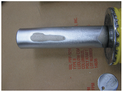
Exhibit 5-3. Poor or partial coverage.
Poor or Partial Coverage
When a part is pulled from the hard chrome plating tank, chromium may not have deposited over the entire plated area. There may be large unplated areas, or just small patches of missed spots (see Exhibit 5-3). This is referred to as "poor coverage."
There are many possible causes of poor coverage; the most likely causes are discussed in this section.
Chemistry Problems
Chemistry problems are the most common cause. Covering power is reduced when the chrome-to-sulfate ratio is too low. For example, consider a standard, single-catalyst bath that has 25 oz/gal of chrome and 0.40 oz/gal of sulfate. This situation can occur quite easily if the plater has not added chrome recently, and the sulfate concentration has gradually risen over time. The chrome-to-sulfate ratio would be 62.5 to 1, which is far too low, and could cause poor coverage.
Even if the chrome-to-catalyst ratio is normal, poor coverage can occur if the chromic acid concentration is too low. This is especially true for baths that have higher than normal levels of trivalent chromium or metallic impurities.
Although it is imperative that you have your bath analyzed on a regular basis, you should also check the bath between analyses yourself using a specific gravity hydrometer (Baumé stick), which will give you a quick approximation of the bath's chromic acid concentration. A chart for converting Baumé readings to chromic acid concentration can be found in Appendix 8. Keep in mind that, unless you have a freshly made bath, Baumé readings give you the maximum possible chromic acid concentration, not necessarily its actual concentration. Both trivalent chromium and dissolved tramp metals also contribute to the reading. Therefore, if you measure 33 oz/gal chromic acid, assume that the concentration is actually something less than 33 oz/gal. Over time, you will be able to compare your specific gravity readings to laboratory data, and you will be able to adjust your readings accordingly. For example, if you measure 33 oz/gal chromic acid and the lab report says the concentration is 31 oz/gal, then begin to subtract 2.0 oz/gal from your future Baumé readings.
Electrical Connectivity Issues
Poor or intermittent electrical contact between the parts and the rack, or between the
rack and tank bus bars can cause coverage problems. This is also true if the rack members are undersized and cannot
carry sufficient current to the parts during plating. And this
is especially true for long plating cycles, where overheating of the rack can increase its electrical resistance.
Between the rectifier and the tank there are usually many connections between bussing and cables. Each connection is a potential source of voltage drop that could cause you to underplate a part, or to have partial coverage.
An easy way of checking for voltage drops is to measure the voltage directly at the anode and cathode using a handheld voltmeter, and compare this to the voltage reading at the rectifier. In a well designed and maintained system, the difference will be only 0.2 V or less. In a system where connections are corroded or undersized cables are used, voltage drops can exceed 1.0 volt. In such cases, you are getting less power to the part than you expect based on the rectifier reading, and could end up with an underplated part. For more information on tracking down voltage drops, see Appendix 9.
Use of Shields, Thieves and Robbers
Because it's hard to deposit completely uniform chromium, platers often use non-conducting plastic shields to limit the electrical communication of certain areas of a part with the anode. Another popular technique is to use metallic thieves or robbers to attract the excess electrical flow. The plastic shields prevent the chrome from reaching the shielded areas, while the thieves or robbers attract chrome away from high current density areas on the part that would have otherwise acquired an excessively thick deposit. Although these techniques are effective, it takes a lot of experience to master their use. When they are not sized or placed correctly, they can even cause some areas to get no deposit at all.
Gassing
Hydrogen gas is given off at the part and at the rack during plating. It is important that this gas breaks free of the surface of the part, and that it rises in an unobstructed manner to the surface of the plating bath. Generally, this is not an issue because new gas bubbles are forming throughout the plating cycle, and they tend to dislodge existing bubbles. However, if hydrogen gas bubbles get trapped, for example under a shoulder, they will prevent the chromic acid solution from coming in contact with that area on the part, causing a missed spot. Also, unplugged holes in a hollow part will gas continuously, which often results in a missed spot above the hole.
Passive Anodes
Passive anodes are a common cause of plating problems, including partial coverage. Passive anodes can be visually
identified by their yellow color, caused by a lead chromate film that forms on the surface. Healthy,
active anodes have a deep brown or black color, which is lead oxide. The portions of
the anode covered with yellow film are much less electrically active and will not contribute significantly to reverse
etching or chromium plating. This can result in underestimating reverse etch and plating times, and ultimately in
misplated parts.
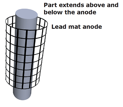
Exhibit 5-4. Conforming anode designed shorter than the part to reduce buildup (including trees) on the ends and improve coverage in the center of the part.
The most frequent cause of passive anodes is inactivity. Stick or other tank anodes that are left in a plating bath without power being applied will become passive. Anodes that are used at low current density and/or are located too far away from the cathode can also become passive. Another common cause is poor connectivity between the anode hook and the bus bar.
Anodes that are only slightly passive, meaning that they are only partially covered with the yellow lead chromate film, can usually be used without any special procedures, although it may be necessary to add some time to the reverse etch step. Once the forward polarity is applied and electroplating is performed, the yellow chromate film will disappear and be replaced by the healthy brown coating. If this does not occur, then there is probably a problem with the connectivity of the anode hook, or the anode to cathode spacing is too far.
When anodes are expected to be inactive for several days or more, they should be removed from the plating tank to prevent them from becoming excessively passive. Alternatively, passive anodes can be activated before use by running dummy parts in the tank before plating production work. Another potential cure is to remove the anodes from the bath, soak them in an anode cleaner solution, and brush off the yellow chromate film with a wire brush. Anode cleaner solutions are typically formulated with Rochelle salts. Also, some shops use spent alkaline cleaner for this purpose.
Anode Placement and Size
Incorrect anode placement (e.g., too great a distance between the anode and cathode) can cause poor or partial coverage. Moving stick anodes closer to the workpiece or using conforming anodes will often eliminate this problem.
Also, reducing the size of the anode area can sometimes make a big difference in coverage depending on the shape of the workpiece. For example, if you are plating a flat surface and you select an anode that is much larger in size, chromium deposits will quickly buildup on the edges, but the center of the part may have zero coverage. To correct this problem, use an anode that is smaller than the surface being plated. The same is true of inside diameters and outside diameters. Use an anode that is slightly shorter than the part to reduce a buildup at the ends and improve coverage.
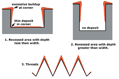
Exhibit 5-5. Examples of expected chromium deposits for various shapes.
Poor Throwing Power
The term "throwing power" refers to the ability of a plating bath to produce deposits in the low current
density regions of a part. These regions are typically farther away from the anode than other areas. For example, a
steel mold that
is concave in shape would have a low current density area in the depression.
With cylindrical parts, such as shafts, the resulting chrome deposit has a "dog bone" contour; thicker chrome on the ends and thinner chrome in the center. This effect can be reduced by using a conforming anode that is shorter than the part, or by masking off the top and bottom of the anode. Other surface shapes are more difficult to deal with, like those shown in Exhibit 5-5. Recessed areas that are wider than they are deep (see #1) can be chrome plated, however, the deposit will be non-uniform. Recessed areas that are deeper than they are wide (see #2) are very difficult to plate. Threads also present problems (see #3); in many cases, the non-uniform deposition of chrome alters the thread diameter and angle.
 |
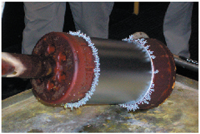 |
| Exhibit 5-7. Trees formed at edges of an OD that is masked with wax. |
Some chrome plating bath formulations have better throwing power than others. For example, a proprietary high-speed, non-etch or fluoride bath will provide better throwing than a conventional, single-catalyst bath. However, for any given plating bath, there are several factors that influence throwing power:
- Chrome-to-catalyst ratio. The chrome-to-catalyst ratio has a significant influence. In the case of a conventional bath, a bath with a 115 to 1 chrome-to-sulfate ratio will throw much better than a bath with a 75 to 1 ratio. The 115:1 bath would do a much better job on molds or dies that have concave shapes or shallow inside diameters.
- Chromic acid concentration. Even if an ideal chrome-to-sulfate ratio is maintained, the chromic acid concentration must not be too low, or throwing power will be reduced. For example, 20-25 ounces per gallon is too low for optimal throwing power, even for a new, clean bath.
- Bath temperature. Cooler baths throw better than hotter ones. For example, a bath at 120°F will throw much better than the same bath chemistry at 140°F. A plating shop could therefore optimize a conventional bath for throwing power by keeping the chrome-to-sulfate ratio at 115:1 and running the bath at 120°F.
- Bath impurities. High trivalent chromium or tramp metal concentrations in the bath will adversely affect throwing power.
Trees
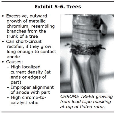
Many platers have saved a collection of chrome trees that they knocked off the edges or ends of parts after long plating cycles. These chrome trees are solid, metallic chromium. They may be shiny and silver-blue like the rest of the chrome deposit, or they may be duller and greyer in appearance.
Chrome trees always grow on regions of the part that experience extremely high localized current density. Although the average current density delivered to an entire part may only be 2.0 amps per square inch, a protruding edge on the end of a part may receive a current density several times higher. This results in the formation of chrome that resembles branches on a tree. Examples of chrome trees are shown in Exhibits 5-6 and 5-7. Chrome trees can be extremely harmful. During long plating cycles, they can "grow" all the way to the anode, causing a short that may damage the part and/or the rectifier.
When plating inner diameters of bores or tubes using ID anodes, tree formation can often be eliminated by increasing the flow of electrolyte through the bore or tube. This also has the added benefit of increasing the plating rate.
Chrome-to Catalyst Ratio
A high chrome-to-catalyst ratio can increase formation of chrome trees. For example, a 115 to 1 chrome-to-sulfate ratio that would improve throwing power in a conventional, single-catalyst bath will have the unwanted side effect of encouraging the growth of chrome trees. This is one of the reasons most shops run these baths at a 100 to 1 chrome-to-sulfate ratio. It's a compromise between a low ratio with minimum chrome treeing and poor throwing power - and a high ratio with good throwing power and excessive treeing.
If the trees cannot be avoided, many platers will remove the part in the middle of a long plating cycle, knock the trees off, and then continue plating the part.
Both ends of the cylindrical part shown in Exhibit 5-6 were masked with conductive tape along the edge of the plated surface. This was done to redirect the growth of chrome trees onto the tape rather than the edge of the plated region. Used in this manner, the conductive tape is a "current robber."
PVC Maskants
Maskants made of machined PVC that replace lead and aluminum tapes at edges will eliminate chrome tree formation (e.g., a PVC collar fitted around the upper and lower edges of a piston). The PVC must closely fit the diameter of the part to prevent chrome from depositing under the PVC, but allow sufficient clearance so that the maskant can be removed after plating. These types of devices, which replace conventional maskants are referred to as no-mask fixtures.
 |
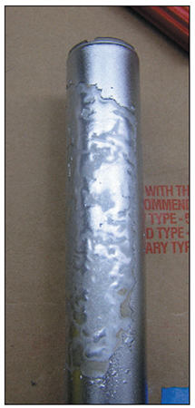 |
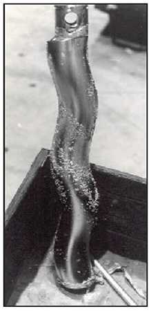
| Exhibit 5-8. PEELED CHROME: A heavy buildup of chrome has blistered, indicating an adhesion problem. | Exhibit 5-9. Picture of peeling and blistering. |
Poor Adhesion
Chrome is usually deposited onto the base metal of the part, a previously-plated chrome layer, or another coating
like nickel. A weak bond between the chrome and its underlying surface manifests itself as peeled or blistered
chrome.
Poor adhesion refers to peeling, blistering or lifting of the chromium deposit from the work piece. It can be caused
by several factors, most of which are related to pre-plate proce-dures. Examples of poor adhesion are shown in
Exhibits 5-8 and 5-9.
Peeled, blistered or lifted chrome are the easiest defects to diagnose and avoid. All you have to do is discover why the preplate surface was not in a condition to accept the chrome deposit with a strong bond.
Cleaning
Inadequate pre-plate cleaning or rinsing may result in a film of oil or maskant (e.g., residual adhesive or lacquer) remaining on the surface of the part being plated. Prior to etching, the surface of the part should be sufficiently clean that it passes the "water break test" discussed in Section 4. Although reverse etching is capa-ble of removing some foreign matter, it should never be relied on as a cleaning technique.
Reverse Etch/Chemical Activation
Inadequate or excessive reverse etching is an-other common cause of poor adhesion. Etching is necessary to assure a good bond between the base metal and chromium deposit. The exact procedure depends mainly on the type of base metal being plated (see Section 4 and Ap-pendix 3). If the surface is under-etched, there may be insufficient roughness of the base met-al to create a strong mechanical bond with the deposit. With over-etching, too much carbon is brought to the surface of the part and a film of blue or gray smut occurs. This film is also not conducive to good bonding.
Not all parts can be reverse etched in chromic acid. Some are etched or activated in chemi-cals like sulfuric acid. However, the same rules apply as with reverse etching in a chrome bath; inadequate or over-processing can lead to poor adhesion.
If you are unsure on how long to etch a par-ticular part (e.g., if you do not know exactly what metal you are plating) you should pro-ceed cautiously and only etch the part for 50% of the expected time. Then, check the part to see if it is adequately etched (i.e., dull surface, but not covered with carbon smut). If adequate etching has not been induced then continue the etching process, but check the part periodi-cally to avoid over-etching. If the part is over-etched, the surface smut should be removed by pumice scrubbing or abrasive blasting be-fore proceeding.
Chromium over Chromium
Poor adhesion often occurs when chromium is plated over an existing chromium deposit. This situation can be avoided
by following
the chrome over chrome plating technique discussed in Section 4. In some cases, when reworking parts, patches of
chromium are in-advertently left on the part due to inadequate chemical stripping or grinding of an old coat-ing.
Since chrome over chrome requires a dif-ferent reverse procedure than chrome on bare steel, this may result in poor
adhesive where the old chromium deposit was present.
Current Interruptions
Interruptions of the electrical current may also cause poor adhesion. For example, power failures may cause the rectifier to shut off for an extended time period (e.g., 5 or more min-utes). If the plating process is restarted with-out further intervention, poor adhesion may result. Therefore, after power failures occur and power is again available, you should follow the chrome-over-chrome reverse etch/plating procedure before continuing. With power inter-ruptions of 5 or fewer minutes plating can usu-ally be successfully continued with no activa-tion step.
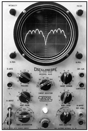
Exhibit 5-10. RECTIFIER DAMAGE: This oscilloscope trace indicates that the SCR power supply has damaged components that can cause peeled chrome. All of the humps should be the same amplitude (height).
Other Causes of Poor Adhesion
Other potential causes of blistering and peeling that have been observed are:
- Rectifier problems such as single phas-ing and high ripple. These can be detect-ed using an oscilloscope (Exhibit 5-10).
- Improper preplate grinding.
- Low bath temperature.
- Failure of maskant along edges, which traps solutions used to clean or activate prior to chrome plating. These are typi-cally seen as "seepage" along an edge on to the area to be chrome plated. Look for maskant adhesion "lift-off" on the base metal.
Roughness
A rough deposit is often the result of a poor base metal condition. Unlike copper plating, which tends to fill in scratches or small holes (this is called leveling), chromium tends to follow the profiles of the part and exaggerate any imperfections.
Therefore, if you have imperfections on the base metal, these will really stand out after chrome plating. Further, any metallic slivers or protrusions of the base metal will act like small lightning rods by attracting excess plating current, and causing localized heavy chrome buildup.
Grinding
An unsuitable base metal profile causes problems with both thin and heavy chrome deposits, but often in different ways:
- In the case of thin deposits, postplate grinding or polishing may expose the steel substrate wherever a steel sliver, nodule or protrusion exists.
- With heavy deposits, the bumps keep getting larger as the deposit grows. This results in a waste of chromium, energy and postplate grinding labor, since the entire plated area has to be over-plated enough for the low-lying regions to clean up to finish size during grinding.
It's much better to invest time and labor as needed to properly prepare the part for plating. Inadequate preplate grinding and polishing will often lead to a rough deposit, surface defects and increased postplate grinding requirements.
Reverse Etch
The reverse etch activation cycle when plating steel parts may affect deposit smoothness. On low-carbon, low-alloy mild steels, under-etching may pull metallic slivers outward, promoting roughness. However, continued reverse etching may serve to electropolish the part, removing much of the protruded steel. Over-etching causes roughness on high-carbon or high-alloys steels if it pulls the carbon or other particles from the case of the steel to the surface. Chrome won't even cover over carbon unless the initial plating current density is very high, and if it does, the chrome will be rough.
Other Causes of Roughness
Other potential causes of roughness include:
- Insoluble materials circulating in the plating bath can get trapped on and in the deposit, causing roughness. This is especially true for magnetic particles, which affix themselves to the surface of the part.
- Highly magnetized parts from mag par-ticle inspection.
- High trivalent chromium or tramp metal concentrations.
- An under-catalyzed bath, where the chrome-to-catalyst ratio is too high.
- Plating at a bath temperature that is too low increases the likelihood of roughness.
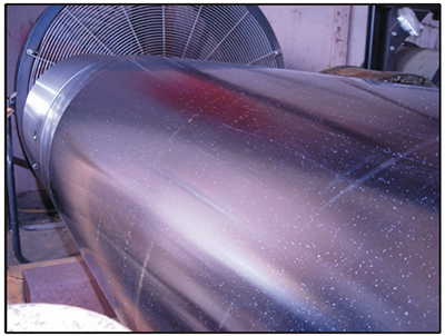
Exhibit 5-11. Long shaft with thousands of pits after plating. These pits were caused by inadequate pre-plate grinding.
Pitting
Pitting is a common defect in hard chromium deposits, and a difficult problem to troubleshoot because there are so many possible causes. A photograph of a long shaft with thousands of pits after plating is shown in Exhibit 5-11. These pits were caused by inadequate pre-plate grinding.
Oftentimes pits that are observed in the plated part were preexisting, but undetected, in the base metal. This occurs because chrome plating magnifies the small defects, making them more easily seen after plating. Good lighting and careful visual examination are needed to find the pits in the base metal prior to plating. Unfortunately, in order to tell whether pits in the chrome plate were preexisting in the base metal, it's necessary to strip the plate and then inspect the substrate.
Sometimes the base metal is just porous, having an entire surface that is riddled with pits, holes or other cavities. Cast iron is a good example of this. Pits can also be caused by inclusions in the base metal, resulting from grinding, polishing or turning operations.
Any foreign material that still resides on the surface of the substrate after cleaning and etching has the potential to cause pitting. Glass bead, marking dyes and carbon smut are examples. Often, these substances will survive aqueous cleaning cycles.
Insoluble material that is suspended in the plating bath will cause post plate pitting if they are dislodged from the chromium deposit in postplate grinding or polishing. Magnetic particles, or particles that would be attracted to a magnetized part, are especially common.
Older-generation chemical mist suppressants, used to minimize the release of chromic acid mist from the surface of the plating tank, sometimes caused pitting. This was especially true for heavy deposits. Modern fume suppressants have been reformulated to minimize or eliminate this tendency.
Hydrogen gas is given off at the part being plated, as a result of the hydrolysis of water in the bath. As these hydrogen bubbles evolve, they must dislodge themselves from the plated surface. If they do not dislodge, the gas bubble serves as a barrier to plating, because chromium ions in solution cannot come in contact with the part. The shape of a pit can help to determine its cause. If the pit is shaped like a tear drop, hydrogen gas pitting is the likely cause. Increasing the electrolyte solution flow past the surface of the part may help to eliminate hydrogen gas pitting. In some situations, this can be accomplished by pumping solution.
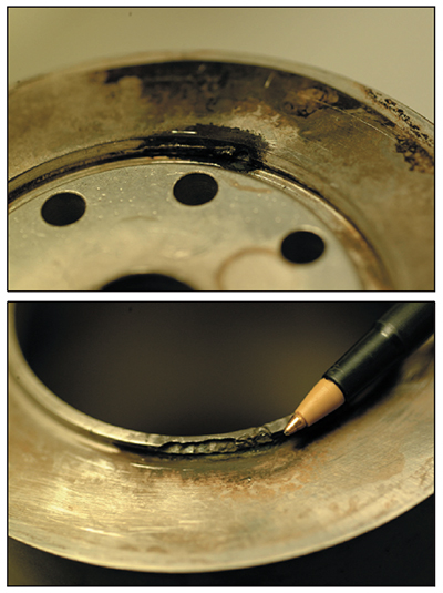
Exhibit 5-12. Arc damage to chrome plated parts.
Arcing
Arc damage can occur to parts during plating if they are not firmly held by fixtures or contact plates. Arcing can lead to severe damage, and often results in a scrapped part. A photograph of arc damage is shown in Exhibit 5-12.
Arcing is mainly attributed to:
- Poor fixture design.
- Not tightening nuts, bolts or other holding mechanisms that secure the part to the fixture plate.
- Dirty contact points (e.g., debris, corrosion, or dried film of chromic acid on contact areas)
Poor Corrosion Resistance
The corrosion resistance of hard chromium plated parts can vary significantly. The chromium deposit has a microscopic crack pattern that forms due to deposit stress, shrinkage and the release of trapped hydrogen. Aggressive elements in the environment can weave a path through the microcrack pattern all the way to the base metal, forming points of corrosion. Some baths deposit chrome with deep, wide microcracks, which promotes corrosion. Deposits that are too thin also increase the chance that corrosion will occur during use.
A high concentration of tramp metals in the plating bath reduces the corrosion resistance of the resulting deposits. Also, the preplate surface profile affects corrosion resistance; a smooth substrate can significantly increase the corrosion resistance of the plated part (see Exhibit 5-13).
Micro-Cracking
Chromium deposits produced from conventional baths that are operated within the "bright range" will be
microcracked. This occurs during deposition due to high stresses in the deposit. As plating progresses, the cracks
are plated over and new cracks occur in the next layer. Microcracking is generally considered a desirable property
since the cracking retains lubricants and gives reduced friction between metal surfaces. However, depending on the
application, the micro-cracking effect attained may be considered inadequate or excessive.
Variations in temperature and the chromium-to-sulfate ratios have a significant influence over the degree of cracking.
Lower temperatures (≤130°F) and ratios (<100:1 chromium-to-sulfate) increase cracking.
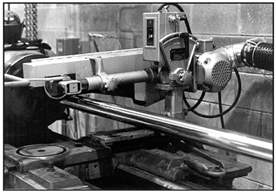
Exhibit 5-13. PREPLATE POLISHING: Smoother profiles can improve the corrosion resistance of the plated part.
Macro (Mud) Cracking
Fine surface cracking is normal in hard chrome but coarser cracking, known as "macro-" or "mud-cracking," or "chicken wire cracking," that is through the full depth of the chrome deposit will result in very poor corrosion resistance. Typically, macro-cracking is not the result of plating, but rather is caused by improper grinding methods.
These include:
- use of the wrong grinding wheel (optimum grit material, grit size and binder should be used),
- incorrect feed or speed (faster is not better),
- too deep of a grinding wheel cut,
- inadequate or the wrong cutting fluid, or
- not dressing the wheel often enough.
For more information, see AMS 2440 (Inspection of Ground, Chromium Plated Steel Parts).
Slow Plating Rates
Typical chromium deposition rates are 0.50 to 0.75 mils thick per hour for stick anodes, and 1.0 to 1.5 mils thick per hour for conforming anodes, using a conventional bath and average bright range settings (i.e., 130 oF, 3.0 APSI). There are a number of factors that can prevent you from achieving these rates:
- Inaccurate rectifier control readout, causing you to plate at a lower than expected amperage or voltage. Use a handheld volt/amp meter and check the actual amperage and voltage at the tank (fixtures, anodes, cables, etc.). Have maintenance performed on rectifier controls if necessary.
- Voltage drop caused by bad connections. This is especially a problem if you
are "plating by voltage." Between the rectifier and the part being plated,
any electrical problems with busing, connections, racks, or cables will result in less actual voltage at the part than is shown on the rectifier control readout. Use a handheld volt/amp meter and check for voltage drops (see procedure in Appendix 9). Have maintenance performed if necessary, including cleaning and repairing connections. - Anode to cathode distance. Use conforming anodes whenever prossible. The anode-to-cathode distance for conforming anodes should be uniform, and within 1 inch or less (larger parts will require a greater distance). Avoid having anodes too close to high current density areas (e.g., use shields on workpiece or anodes).
- Unmasked racks and fixtures connected to the part steal current. Plastisol coat or use vinyl tape to mask the bare metal surfaces of racks and fixtures.
- Low current density and related bath temperature considerations. Faster chromium deposition is attained at higher current densities. However, plating at higher current densities requires that the bath temperature be set in the upper end of the normal range (see Exhibit 5-2). Maximum plating rates for acceptable deposits (bright range) are attained at approximately 4 to 5 APSI with a bath temperature of 140 to 145°F. However, many parts cannot be plated and fixtures cannot be operated at these maximum settings without producing roughness, uneven plating or other unwanted conditions.
- Low chromium concentration and/or low chromium-to-catalyst ratio. Analyze the plating bath for chromium and catalyst (e.g., sulfate). Make adjustments, as necessary to correct concentrations and the chromium-to-catalyst ratio.
Uneven Chromium Deposition
Most hard chrome plated cylinders come out of the tank with an "hour glass" shaped deposit (i.e., thicker on the ends than the middle) or it is thicker at one end. In some cases the uneven deposition is overly exaggerated, causing a need for excessive plating time to achieve a minimum chromium thickness over the entire part. This condition is usually caused by inadequate cathode connections for carrying current. It is especially noticeable with certain aerospace steels where the voltage drop in long thin-walled parts can be very substantial. It is also more likely to occur with stick anodes than with conforming anodes. To minimize the hour glass shape, use conforming anodes and cathode current insertion points at both ends of the part and at other points, if necessary.
Wild Chrome
Inappropriate masking materials and/or poor masking techniques can lead to the lifting or loss of maskants during plating. This will cause unintended deposition of chromium (i.e., wild chrome). Even good maskants such as metal or plastic tapes, lacquers, and waxes have a tendency to be removed during plating when long plating cycles (>4 hours) and higher bath temperatures are encountered. To avoid this problem, use no-mask conforming anodes. Otherwise, optimize and standardize masking techniques and/or reduce bath temperature.

