
Section 5
Chemical Solution Maintenance
5.1 INTRODUCTION
Chemical solution maintenance includes a range of pollution prevention practices and technologies that preserve or restore the operating integrity of metal finishing process solutions, thereby extending their useful lives. Some forms of solution maintenance, such as filtration, have been utilized nearly as long as metal finishing itself. However, due to rising costs for chemicals, energy and treatment/disposal and increasingly more stringent environmental requirements, solution maintenance has become a greater priority to plating shops and the methods and technologies they employ have increased in sophistication. Today, firms are willing to expend significant amounts of capital and operating funds for equipment and methods that primarily reduce the disposal frequency of their baths.
In addition to extending bath lives, solution maintenance often improves the average operating efficiency and effectiveness of a process solution and therefore has a positive impact on production rates and finish quality.
Metal finishing solutions are subjected to a variety of forces that cause them to become unusable. The key contributing factors are: (1) depletion of bath chemicals; (2) chemical break-down of process chemicals or chemical side reactions; (3) contamination from impurities in make-up water, chemicals or anodes; (4) anodic/cathodic etching of parts and inert electrodes; (5) corrosion of parts, racks, bussing, tanks, heating coils, etc.; (6) drag-in of non-compatible chemicals; (7) buildup of by-products (e.g., carbonates); (8) breakdown of maskant, fume suppressant and wetting agents; (9) errors in bath additions; and (10) airborne particles entering the tank.
Solution maintenance replaces the practices of: (1) using a chemical solution until it is degraded and replacing it with fresh solution or (2) decanting a portion of a degraded solution and replacing it with fresh solution. In both cases, the spent solution is usually either treated on-site or transported to a treatment/disposal facility. On-site treatment is not always possible because concentrated wastes may upset treatment facilities designed primarily for treating dilute rinse waters. In some cases, shops are able to reuse spent solution for either: (1) a less critical process application or (2) as a treatment reagent (e.g., spent acid cleaner used in place of sulfuric acid for pH adjustment). The former of these uses is regarded as a pollution prevention option by EPA. The latter method may reduce the overall use of chemicals at a shop, but because it involves treatment, it is not considered "pollution prevention" by EPA. EPA's definition of pollution prevention is presented and discussed in Section 3.
Two major categories of solution maintenance have been identified during the NCMS project: preventative and corrective. Within this text, preventative solution maintenance refers to the practices that avoid bath contamination or involve monitoring and adjusting of solution chemistry. Corrective solution maintenance refers to the practice of removing contaminants from the bath, whether they are dissolved or particulate, organic or inorganic. Both preventative and corrective solution maintenance involve the use of methods, techniques and technologies. Methods and techniques are typically procedural in nature or low capital items that can be implemented quickly and have an almost immediate payback. Technologies are generally equipment packages that have a moderate to high capital cost and payback periods of one year or greater. Most preventative measures are either methods or techniques. However, some technologies such as an electroless nickel bath automatic replenishment system would also fall into this category. Corrective measures include both methods/techniques such as dummy plating and technologies such as microfiltration.
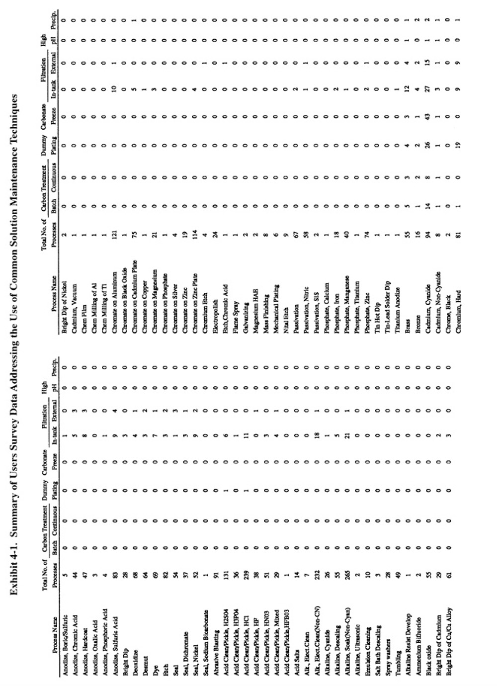
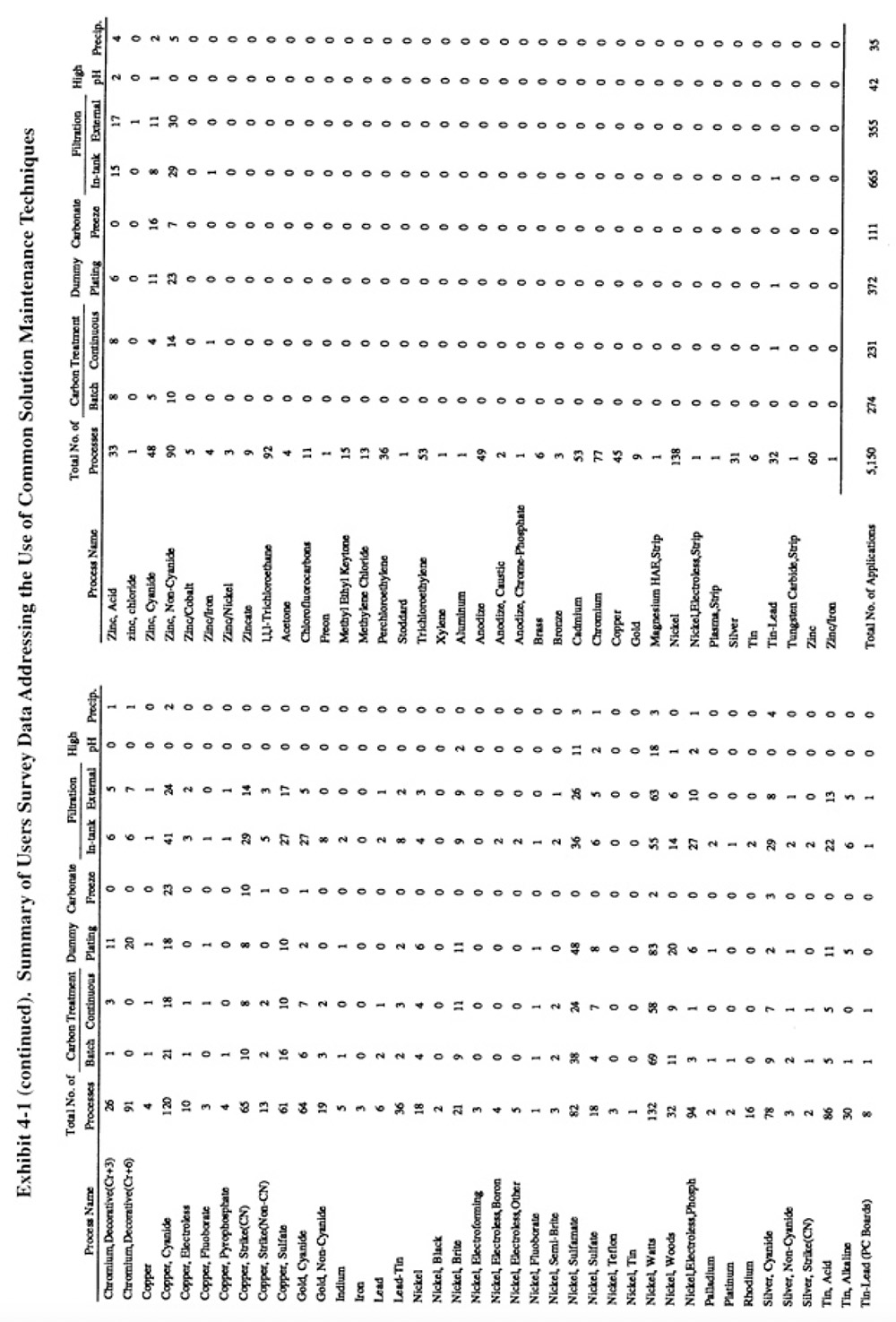
Methods of preventative and corrective solution maintenance that are commonly applied by plating shops, and therefore do not require a detailed discussion, are reviewed in Section 5.2. The corrective technologies, which are generally less familiar to platers, are covered in detail in Sections 5.3 through 5.8. Exhibit 5-1 presents the results of the Users Survey that show the frequency of use for each of the common corrective bath maintenance techniques.
The information contained in Sections 5.3 through 5.8 is derived from the results of the Users Survey, Vendors Survey and literature search. The Users Survey requested platers to provide detailed technical, performance and operating cost data for bath maintenance technologies. The vendors were requested to provide technology descriptions, operating data and capital cost data. As a result of obtaining data from these two sources, plus the information from the extensive literature review, Section 5 contains a substantial quantity of information for the following corrective bath maintenance technologies: microfiltration, ion exchange, acid sorption, ion transfer, membrane electrolysis and diffusion dialysis. A separate subsection of the text is devoted to each of these technologies. Within each subsection, the following are provided: technology overview; development and commercialization; applications and restrictions (with diagrams showing different potential configurations); technology/equipment description; capital costs; operating costs; performance experience; and residuals generation. The capital cost curves contained in Section 5 are based on data collected from the technology vendors and the operating cost curves are based mainly on data from platers. Both the capital and operating cost information are expressed in 1993 dollars. A labor cost of $25 per hour (includes overhead) and an electricity cost of $0.10/kWh have been used, where applicable, in calculating operating costs.
5.2 COMMONLY APPLIED PREVENTATIVE AND CORRECTIVE BATH MAINTENANCE TECHNIQUES
5.2.1 Common Preventative Measures
Preventative methods for extending the life span of plating and other metal finishing baths were covered in Section 3.3 as part of the discussion of good operating practices. A summary of these methods, is contained in Exhibit 3-19. The following subsections address common corrective bath maintenance techniques.
5.2.2 Common Corrective Measures
5.2.2.1 Filtration
Filtration is the most commonly applied method of corrective bath maintenance. It is used to remove suspended solids from plating and other metal finishing solutions. Suspended solids in plating solutions may cause roughness and burning of deposits. Various equipment are used for filtration, with the most common being cartridge filters and precoat (diatomaceous earth) filters. Sand or multimedia filters are also employed. Cartridge filters are available with either in-tank or external configurations, with the former used mostly for small tanks and the latter for larger tanks. Most cartridges are disposable, however, washable and reusable filters have been recently commercialized. Several respondents reported use of the reusable filters (PS 180, PS 265, PS 229). Precoat filters are used mostly for large tank applications. Filter media are selected based on the chemical composition of the bath. Filtration systems are sized based on solids loading and the required flow rate (turnovers per hour). Typical flow rates for plating solution applications are 2 to 3 bath turnovers per hour. Other operating criteria for filtration processes can be found in the literature (ref. 421).
A total of 1,020 applications of bath filtration were reported by the 318 respondents of the Users Survey or an average of 3.2 per shop. Approximately two thirds of these filtration applications involved the use of the less expensive in-tank devices and one-third the external devices. The distribution of filtration applications among the different types of plating baths was approximately the same as the usage of the baths themselves (see Exhibit 5-1 which indicates for each process the total number of plating processes and the number of filtration applications identified). One notable exception was chromium plating, where filtration was not frequently applied.
Cost data for common bath maintenance techniques were not specifically requested during the Users Survey. However, four shops provided the following data for filtration.
PS 160 reported a capital cost of $14,000 (l991 costs, includes $1,000 of installation costs), annual non-labor costs of $2,000 and an annual labor requirement of 50 hours for an external sand filtration system (Techmatic) that serves three zinc chloride tanks containing 7,600 gal of solution. They reported that the sand bed requires manual stirring once per month and that the sand must be replaced once each year. They indicated that the downtime of the unit was 2% and reported a high satisfaction level for the filter.
PS 191 reported that they have purchased multiple filter units (Serfilco) that had a total capital cost (purchased during various years dating back to 1965) of $40,940 (includes $3,000 of installation costs) to filter two nickel plating tanks totaling 7,200 gal. They employ standard filter cartridges, but rather then discard them after a single use, the spent cartridges are washed in a standard washing machining (inexpensive Sears unit). They have found that by washing the cartridges (after first soaking them in a tank), they can reuse them 3 to 4 times. They expend approximately 30 man-hrs per year washing cartridges. They first implemented this procedure in 1989 and had to replace the washer in 1992. The discharge from the soak tanks and the washer is sent to their conventional treatment system. They originally implemented this procedure in order to dispose of the filters as nonhazardous waste, but after seeing the results of the cleaning process, decided to reuse them. Used anode bags are processed in the same manner.
PS 114 reported the purchase of used filtration equipment for $500 with installation costs of $350 (1992) for filtering an electrocleaner and acid pickle (105 gal each). They indicated that annual non-labor costs are $100 and the labor requirement is only 10 hrs/yr. They estimated that by using filtration, they extend the life of the electrocleaner by 10 times and the life of the acid pickle by 5 times.
PS 253 reported cost data for a carbon treatment/filtration system (see Section 5.2.2.2).
5.2.2.2 Carbon Treatment
Carbon treatment of plating baths is a common method of removing organic contaminants. The carbon adsorbs organic impurities that are present as a result of oil introduction or the breakdown of bath constituents. It is used on both a continuous and batch basis. Various application methods are available, including carbon filtration cartridges (contain up to 8 oz of carbon and are restricted to use on small applications), carbon canisters (up to 10 lbs of carbon), precoat filters, and bulk application/agitation/filtration (ref. 421). Typical dosages are 1 to 4 pounds of carbon per 100 gallons of solution (ref. 341, 421).
A total of 505 applications of carbon treatment were reported by respondents to the Users Survey. The most frequently cited applications were nickel electroplating (mostly Watts nickel and nickel sulfamate), which accounted for 50% of all carbon treatment applications. The other most common applications were copper electroplating (18% of all applications) (mostly copper cyanide and copper sulfate), zinc plating (10% of all applications) and cadmium cyanide plating (4% of all applications). Survey respondents used continuous (46%) and batch (54%) carbon treatment methods on an almost equal basis.
Cost data were not requested in the Users Survey for common bath maintenance techniques. However, two shops provided the following data for carbon treatment. PS 253 reported a capital cost of $14,200 (installed cost for external Mefiag 6500 SS filter/carbon treatment system,1986), non-labor annual costs of $616 and 39 hours/yr of labor for maintaining a 3,600 gal Watts nickel bath. The bath is continuously pumped through a carbon filter at a rate of 55 gpm. This operation generates 125 lbs/mth of spent filter pads which are sent to off-site disposal. PS 253 indicated that they are very satisfied with the unit and that it has a downtime of 0%. PS 160 reported a capital cost of $120 (1992) for an in-tank unit (Flo-King) and annual operating costs of $240 (includes both labor and non-labor costs). They indicated that they are satisfied with the unit and that it has a downtime of only 2%.
5.2.2.3 Electrolysis (Dummying)
Dummy plating is an electrolytic treatment process in which metallic contaminants in a metal finishing solution are either plated out (low current density electrolysis) or oxidized (high current density electrolysis). Dummy plating has been documented to be in use since 1916 (ref. 339).
Low current density (LCD) dummy plating is applied to a range of plating and other metal finishing processes. The contaminant metals that are most frequently removed by dummy plating are copper, zinc, iron and lead. Dummy plating is usually performed using a corrugated steel sheet cathode with an anode to cathode spacing of approximately 4 in. The optimal current density will depend on the metal contaminants being removed. The normal range is 2 to 8 ASF. The duration of treatment is typically 2 to 5 amp-hr/gal. Agitation is essential for speedy removal of contaminants and air agitation should be used if the type of bath permits (ref. 270, 339, 340, 341).
LCD dummy plating can be performed on a batch or continuous basis. Batch treatment is usually performed in the process tank and requires down-time. Continuous treatment is usually performed in a side-tank and cathodes are typically sized to permit 0.05 amp/gal of solution (ref. 339, 341). The solution is preferably returned to the process tank through a filter (ref. 314). An example of a continuous LCD dummy plating application used by PS 118 on a closed-loop nickel plating line is shown in Section 3.4.
High current density (HCD) dummy plating typically refers to the practice of oxidizing trivalent chromium to hexavalent chromium in chromic acid baths (e.g., chromium plating and chromic acid anodizing). It is also used to gas-off chloride as chlorine.
The HCD process requires an anode to cathode ratio of between 10:1 and 30:1. Lead or lead alloy anodes are typically used in the process. A lead peroxide film is formed on the anode which functions as the oxidation agent. Current densities of between 100 to 300 ASF are used. The rate of conversion is controlled by the overall cathode and anode areas and current flow.
Respondents to the Users Survey employed dummy plating most frequently with nickel electroplating (48% of all electrolysis applications), chromium electroplating (13%), zinc electroplating (11%), copper electroplating (10%) and cadmium electroplating (7%).
5.2.2.4 Carbonate Freezing
Cyanide baths are adversely affected by carbonate buildup. Carbonates are formed by the breakdown of cyanide
(especially at high temperatures), excessive anode current densities and the adsorption of carbon dioxide from the
air. Excessive cabonates cause increased resistance in the bath, yielding low plating current densities, which
normally accentuate the poor appearance that metallic impurities cause. An excessive carbonate concentration can
affect the smoothness of deposits, plating efficiency and plating range. Both sodium and potassium baths are
affected by carbonates. However, the sodium bath is affected at a much lower concentration (14 oz/gal vs 40 oz/gal)
(ref. 340, 482).
Sodium cyanide baths can be treated for excessive carbonate buildup by "carbonate freezing" or
crystallization. Potassium cyanide baths must be treated by precipitation, which is also applicable to sodium
cyanide baths (see Section 5.2.6). Carbonate freezing takes advantage of the low solubility of carbonate salts in
the sodium cyanide bath. The method involves lowering the bath temperature to approximately 26°F (-3°C) where
hydrated salt/Na2CO3 • 10H2O crystallizes out. This treatment procedure will also remove sodium sulfate and sodium
ferrocyanide (ref. 339).
A total of 111 applications of carbonate freezing were reported by the respondents to the Users Survey. The vast majority of the applications were for cadmium cyanide plating, copper cyanide plating and copper cyanide strike baths.
5.2.2.5 Precipitation
Various chemical treatments of plating baths are performed to remove bath contaminants via precipitation. Precipitation is generally a batch process that is often performed in a spare tank where the solution is chemically treated and filtered and returned to its original tank. Electrolytic purification is sometimes applied following chemical treatment to remove metal contaminants less affected by precipitation (e.g., following purification of a Watts nickel bath to remove copper, zinc and cadmium). Precipitation is an alternative method to carbonate freezing for cyanide baths and is especially applicable to potassium cyanide baths. Chemicals used for this purpose include: barium cyanide, barium hydroxide, calcium hydroxide, calcium sulfate or calcium cyanide. The least expensive of these chemicals, calcium sulfate, forms a bulky precipitate that is less easily removed. Other relatively common uses of precipitation include lime addition for the removal of carbonates from silver cyanide baths, sodium sulfide treatment of cyanide baths for zinc and lead removal and nickel carbonate (1 to 2 lbs/100 gal) or nickel hydrate treatment of nickel plating baths to remove miscellaneous metal contaminants (e.g., iron, aluminum, silicon). The latter of these methods is termed "high-pH treatment." Peroxide is sometimes added during high-pH treatment to enhance precipitation and destroy organics (ref. 340). Hydrogen peroxide is also used for oxidizing soluble ferrous iron to insoluble ferric hydroxide in acid chloride zinc baths (ref. 340, 482). Two respondents reported the use of potassium permanganate (oxidizing agent) for iron removal from zinc baths (PS 076, PS 268). The precipitated iron is removed by filtration. Also, lime is sometimes used to remove phosphorus compounds from electroless nickel solutions; however, this process is not widely applied (ref. 286). One respondent reported the use of silver oxide to precipitate chloride from a decorative chromium bath (PS 162).
Respondents to the Users Survey reported 35 applications of precipitation and another 42 applications of high pH treatment. The use of high-pH treatment was restricted mostly to Watts nickel and sulfamate nickel baths. Other precipitation applications in order of decreasing frequency include: zinc plating, nickel plating, silver plating, copper plating, bronze plating, chromium plating and cadmium plating.
5.3 MICROFILTRATION
5.3.1 Overview
Microfiltration is a relatively new bath maintenance technology that is applied to aqueous and semi-aqueous degreasing and cleaning baths for the removal of oil and grease. Only one respondent to the Users Survey (or 0.3%) reported the utilization of microfiltration for this application (end-of-pipe applications of microfiltration and ultrafiltration are discussed in Section 7). Respondents to the Vendors Survey indicate that hundreds of degreasing and cleaning bath applications of microfiltration have been installed. The discrepancy between the Users Survey and the Vendors Survey with regard to the use of this technology is most likely caused by the fact that most respondents to the Users Survey are electroplating job shops. According to the vendors, most microfiltration/degreaser applications are found in captive electroplating shops and non-plating facilities such as metal-working and painting shops. Also, this technology is finding use in the printed circuit board industry for recovering semi-aqueous cleaning agents from rinse water (e.g., as part of the defluxing process) (ref. 515).
In part, electroplating job shops use solvent cleaning less frequently than captive shops because many of them receive parts for plating that have been pre-cleaned and in these cases do not require as much heavy duty cleaning or degreasing. Also, the majority of the job shop respondents that used solvents at one time eliminated their use by substituting aqueous cleaners before the time when the microfiltration technology (as applied to aqueous degreasing baths) was commercially available to them (circa 1988). Most of these shops have implemented a scheme that is technically and economically satisfactory, a condition that does not promote change. Generally, the alternative approach to maintenance is to operate pre-cleaning and cleaning baths to exhaustion and either treat them on-site or haul the spent baths to off-site treatment/disposal. Also, some shops use simple oil skimming and particulate filtration to extend bath life. Conversely, a large percentage of captive shops, painting and metal-working facilities, in response to regulations, have only recently moved to eliminate chlorinated solvent use. The pre-cleaning requirements for many of these plants are more demanding and the substitution of aqueous cleaners has therefore been slower and has coincided with the advancement of microfiltration technology. Additionally, the captive facilities generally have more capital available for the purchase of equipment.
Aqueous degreasing solutions are essentially a mixture of surfactants, alkali salts, caustic soda, phosphates, silicates and complexing agents. Aqueous degreasing and cleaning baths buildup concentrations of oil, grease and soils during use. Free oils can be removed by simple skimming and most solids can be removed by settling and/or cartridge filtration. However, emulsified oils and colloidal solids are not affected by these devices. At some point, the cleaning efficiency of the bath is impaired and the solution is discarded, despite the fact that most of the bath's constituents are still usable. In many cases, heavy duty cleaners must be replaced once per week. The microfiltration technology separates the emulsified oils from the aqueous cleaning solution, thereby extending the life of the bath. This technology is also applicable to the recovery of cleaning solution dragout from rinse waters. However, it is used much less frequently for this purpose.
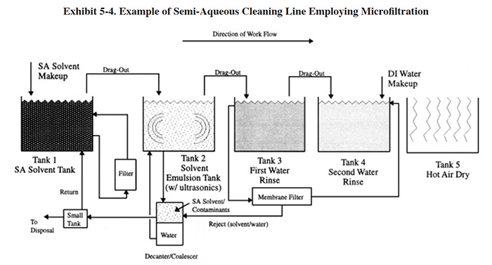
In the semi-aqueous process, parts are cleaned in an organic solvent (e.g., Dupont's Axarel®, or various terpene cleaners) and subsequently rinsed in an emulsion rinse (rinse water and solvent), followed by a water rinse(s). The bulk of the cleaning solvent can be separated from the emulsion rinse by decantation and returned to the solvent cleaning tank. However, some of the solvent is carried into the water rinse. The semi-aqueous process can be operated in a near closed-loop fashion by separating the solvent from the rinse water using microfiltration, returning the solvent to the process tank and recirculating the rinse water. Although this application of microfiltration is better categorized as recovery/recycle than bath maintenance, it is discussed in this section because the equipment used for this application is similar to that used for aqueous cleaner bath maintenance.
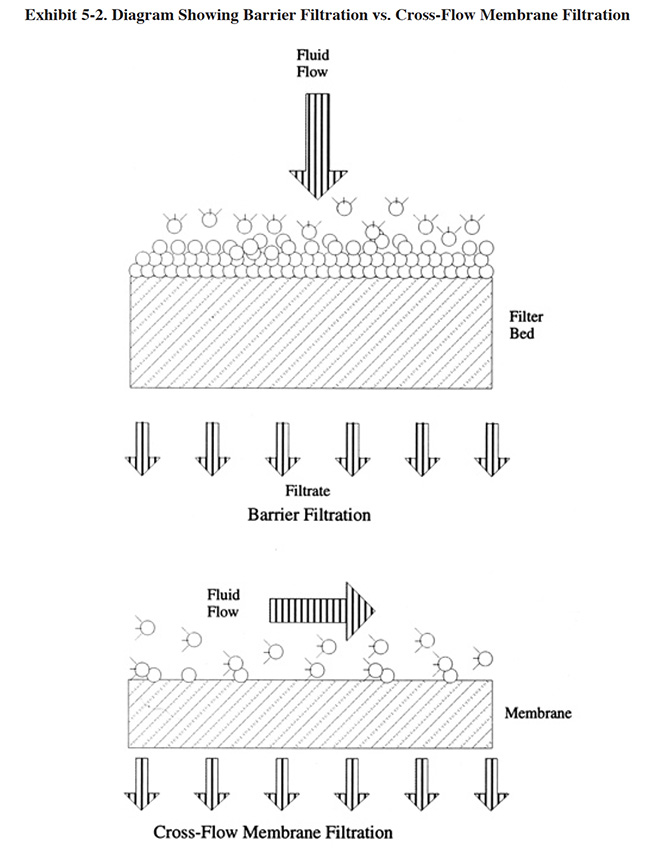
Most commercial microfiltration systems used for this application employ ceramic filter membranes in a crossflow filtration configuration. These membranes are a new development that permits application of microfiltration to solutions and emulsions that are both heated and corrosive. Earlier efforts using polymeric membranes were unsuccessful with this application (ref. 311). The polymeric membranes deteriorate due to the high temperatures encountered and the corrosive nature of the cleaning solutions. Also, the polymeric membranes cannot be cleaned on-line with an air back-pulse, like the ceramic membranes can. The ceramic membranes are produced in a range of pore sizes that selectively permit a large percentage of the surfactants to pass through the membrane (a typical pore size is 0.8 μ and most filters have pore sizes greater than 0.2 μ). Crossflow filtration, as opposed to barrier or "dead-end" filtration, permits the application of this technology to high solids-feed streams. As shown in Exhibit 5-2, in dead-end filtration, all of the feed solution is forced through the membrane by an applied pressure. With a high solids-feed stream, the pores of a dead-end filtration device plug. With crossflow filtration, the fluid to be filtered is pumped across the membrane, parallel to its surface. By maintaining a high velocity across the membrane, the retained material is swept off the membrane surface. This mode of operation typically requires multiple passes and consumes a greater amount of energy than with dead-end filtration. However, for high solids applications, crossflow is the only practical method (ref. 380).
5.3.2 Development and Commercialization
Although the historical roots of membrane filtration extend back to the eighteenth century, commercial and industrial applications did not emerge until the 1900's. Early investigators experimented with animal bladders serving as membrane filters. In latter work colloidal (nitrocellulose) membranes were used, and by 1906 a technique was devised to prepare nitrocellulose membranes of graded pore size. By the 1930's, mircroporous colloidal membranes were commercially available. During the next 20 years, other polymers were used, particularly cellulose acetate. These were used by the end of World War II for testing questionable drinking water supplies in Germany and other parts of Europe where water supplies had been damaged by the war. Research to develop these filters, sponsored by the U.S. Army, was later exploited by Millipore Corporation, the first and largest microfiltration membrane manufacturer. New developments in this area were limited until the U.S. Department of Interior sponsored research in reverse osmosis for desalination. These efforts also assisted the development of microfiltration, ultrafiltration and electrodialysis. A tremendous change occurred in this industry during the time period from 1960 to 1980. Advanced technologies were produced employing high performance membranes that were more chemically stable and mechanically sturdy than their predecessors. Also, membrane module design was advanced, with the development of the spiral-wound, hollow-fine-fiber, capillary and plate-and-frame modules. Application of the technology to degreasing and cleaning baths did not successfully occur until the development and commercialization of the ceramic membrane. These membranes, which were originally used in the food and beverage industry, could easily resist the temperatures and chemicals associated with the degreasing and cleaning baths. Also, they can be cleaned without shutting down the filtration process by back-pulsing the filter with air.
Although this application of microfiltration is fully commercialized, by no means is its development stagnant. Some respondents to the Vendors Survey indicated that equipment modifications are constantly being made to improve the process, expand its applicability, and to make it more cost effective.
5.3.3 Applications and Restrictions
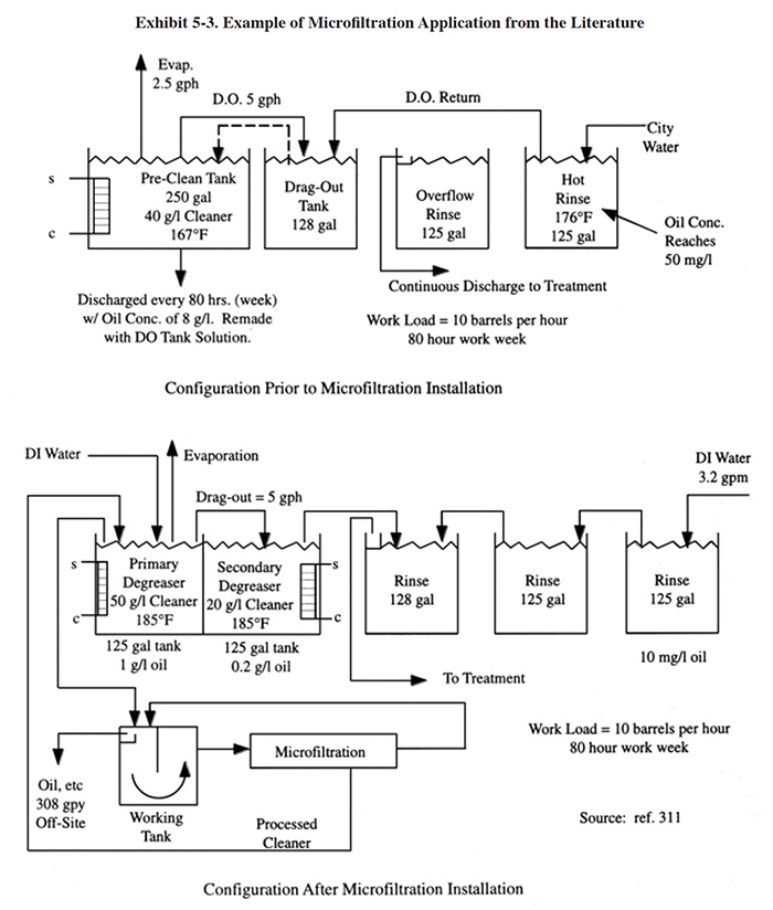
The application of microfiltration to an aqueous degreasing operation is shown in Exhibit 5-3, which is based on a case study presented by Schwering, Golisch and Kemp (ref. 311). This application was a retrofit to an existing metal cleaning line. Prior to conversion (see top diagram), the degreasing bath was discarded after 80 hours of operation when its oil content reached 8 g/l. The bath was remade using the solution in the dragout tank as make-up. The conversion (see lower diagram) consisted of dividing the degreaser tank into two sections, changing the rinsing configuration and adding a microfiltration unit to maintain the solution in the first degreaser section. The concentration of cleaner in the first section (primary degreaser) was increased to 50 g/l and the temperature was raised to 185°F. The concentration of cleaner in the second section (secondary degreaser) was set at 20 g/l. With the installation of the microfiltration unit, a constant oil concentration of 1.0 g/l was maintained in the primary degreaser and 0.2 g/l oil in the secondary. The final rinse contained 10 mg/l oil when operated with a 3.2 gpm feed rate (67 lbs/yr oil). In addition to the rinse water discharge, 308 gpy of oil and contaminants (30% emulsion) were discarded off-site.
Microfiltration is not applicable to all aqueous degreasing and cleaning applications. Usually, shops implementing this technology must consider changing to an alternate cleaner. The most applicable type of cleaner is a simply structured non-silicate cleaner that operates in the higher temperature range (160° to 175°F or 70° to 80°C) and that can easily be replenished with additives (ref. 311). As suggested by Schwering, Golisch and Kemp, cleaners that are particularly well suited for recycling are ones that emulsify oils at the high temperature range and then have the ability to release these emulsified oils at lower temperatures and during plant shutdown (ref. 311).
Cleaning formulations with a high silicate content are generally less amenable to microfiltration recycle. These cleaners contain colloidal silicic acid, which has a tendency to plug the pores of the ceramic membrane (ref. 311). However, the only respondent to the Users Survey that employs this technology operates a bath formulated with sodium metasilicate.
Microfiltration is not applicable to aluminum cleaning solutions since the dissolved aluminum concentration will buildup over time because it will be unaffected by the filtration process.
An application of microfiltration to semi-aqueous cleaning is diagrammed in Exhibit 5-4. The semi-aqueous (SA) solvent tank contains 100% solvent. In this tank, soils are dislodged and/or dissolved in the solvent. Agitation (e.g., pumping) and heat can be applied to minimize the cleaning time. Following the cleaning step, the parts are transferred to the emulsion tank. Air knives are sometimes employed to minimize the carry-over of solvent. The emulsion tank contains a relatively high concentration of semi-aqueous cleaning agent. The concentration is maintained at a relatively constant level by employing a decanter/coalescer to separate the solvent and water. The solvent is returned to the solvent tank (except for periodic blowdown) and the water is returned to the emulsion rinse. A low solvent concentration in the emulsion rinse is desired in order to minimize the carry-over of solvent to the water rinses. However, the lowest practical emulsion concentration is the minimum concentration that will separate in the decanter (e.g., the minimum concentration for DuPont's Axarel® is about 2 percent) (ref. 515). Ultrasonics and mechanical agitation (pumping) are often used in the emulsion tank to improve the efficiency of rinsing. Subsequently, parts are transferred to water rinses (usually two rinses connected in a counterflow configuration). Again, air knives are often used to minimize the carry-over of dragout. The water rinses remove the vast majority of the remaining solvent from the parts. Due mainly to the presence of the organics in the rinse water, firms sometimes separate the solvent from the rinse water using microfiltration, recover the solvent and recycle the water. Competing technologies for this application include carbon treatment and ion exchange.
5.3.4 Technology/Equipment Description
5.3.4.1 General
Equipment selected for this application should have a simple mechanical configuration and be physically sturdy and compact. The materials of construction, including gaskets and seals, must be resistant to high alkalinity, high temperature and sharp temperature fluctuations. Soils and fine metal shavings must not impede the proper functioning of the system (ref. 311).
The available systems typically have two sections within their equipment package. In the first section, free oil and settleable solids are separated from the remaining feedstream. The second section houses or is connected to the microfiltration unit. A key element of the design is the membrane cleaning function. This can be achieved by a pulsing valve fitted into the permeate line. Compressed air is periodically cycled into the permeate discharge line to generate a series of back pulses, creating a momentary (e.g., 0.5 seconds) reversal in the direction of the permeate flow (ref. 311). This prevents solids from fouling the membrane.
The performance and sizing of microfiltration systems is dependent primarily upon the specified flux. The flux is the amount of flow per unit time that will permeate a unit of area of filter space. U.S. industry usually expresses flux as gallons per square foot of filter space per day (gfd). The selection of the membrane and designation of the pressure, retenate flow rate, and concentration of oil in the influent are the most critical factors for proper system operation (ref. 477).
5.3.4.2 Commercial Equipment
This subsection contains a description of commercially available microfiltration equipment used for degreasing/cleaning bath maintenance. This is intended to provide the reader with information and data on a cross section of available equipment. Mention of trade names or commercial products is not intended to constitute endorsement for use.
U.S. Filter markets a bath maintenance system, Membralox® 3000, which is applicable to aqueous and non-aqueous degreasing/cleaning baths. It is a packaged unit requiring a 24 in. by 40 in. floor space. It utilizes ceramic membranes with pore sizes ranging from 500 angstroms to 0.8 microns, depending upon the chemical make-up of the bath. Systems using membranes with pore sizes of 0.2 microns and larger contain an integral backpulsing system to help prevent plugging of the filter membrane. In operation, the contaminated cleaner enters a two-compartment holding tank through a bag filter which initially removes large particulate material from the feed stream. The level in the tank is maintained by a level switch, which controls the tank inlet valve and also acts as a low-level cutoff for the system pump. The oils accumulate in the initial compartment and can be drained on a periodic basis. The liquid then moves to a second tank compartment through a sub-surface passage, thereby leaving the floating oils in the first compartment. The liquid in the second compartment is pumped through the ceramic filter. The water and cleaner chemicals are forced through the ceramic membrane, while the oil and other soils are retained and recycled back to the initial tank compartment. A range of system capacities is available for feed stream flow rates of 300 gpd to 1,500 gpd. The flux rate of the membrane is approximately 50 to 100 gfd. The expected membrane life is 10 or more years.
Kinetic Recovery Corporation markets a cleaner purification system (CPS). A diagram of their equipment is shown in Exhibit 5-5. The contaminated cleaner enters the system through a tank compartment (1) that provides laminar flow conditions due to the presence of baffles. Oil accumulates in the tank and is periodically drained (2). The liquid then moves into the main tank compartment (3) (working tank) from where it is pumped by the immersed pump (4) through the ceramic membrane (5). The water with the dissolved cleaner chemicals are forced through the membrane while the oil and solids are retained and moved to the laminar flow compartment (1). The dirt and solids (sludge) which settle to the bottom of the tank can be periodically drained (6). The continuous operation of the system provides a constant stream of purified cleaner back to the cleaner bath.
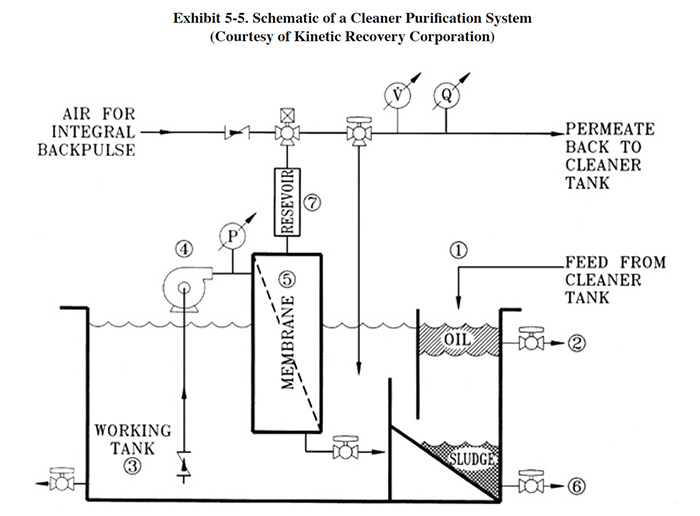
The CPS utilizes microfiltration membranes (pore sizes of 0.2 μ or higher) and contains an integral back pulsing
system to prevent plugging and fouling (impurity layer on the surface of the membrane). The integral back pulse is
an air purge that forces permeate from the reservoir back through the membrane without pushing air into the
membrane. This purge takes only a fraction of a second. Dirt and solid impurities end up as slurry at the bottom of
the tank and are drained off.
Prosys Corporation manufactures microfiltration equipment for various applications, including: recycle of caustic
cleaner, end-of-pipe treatment, polishing of treated effluent, vibratory media filtration, zyglo removal, and
coolant recovery. They have been marketing equipment to the plating industry since 1987 to which they have sold over
70 microfiltration units.
5.3.5 Costs
5.3.5.1 Capital Costs
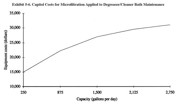
Equipment costs for microfiltration units applicable to the maintenance of cleaning/degreasing baths are presented in
Exhibit 5-6. These costs are based on the use of the ceramic membrane technology with a flux rate of approximately
50 to 100 gfd. Equipment sizing is heavily dependent on the oil and soil loading of the bath. A 300 gpd
microfiltration unit will typically maintain a cleaning/degreasing bath that is processing 10,000
ft2/week of parts coated with machining oil.
Installation costs for microfiltration units are estimated to be 10% to 30% of the equipment costs.
5.3.5.2 Operating Costs
Operating costs for microfiltration have not been estimated due to the limited number of installed systems and the limited availability of operating data. Operating costs, including labor, reported by one respondent to the Users Survey are given in Section 5.3.6.
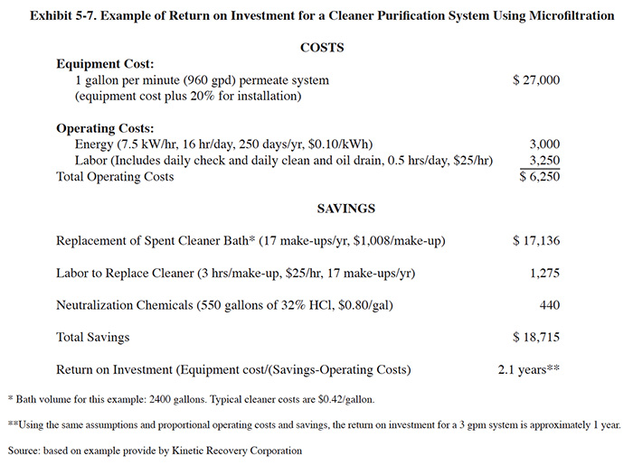
Kinetic Recovery Corporation, a vendor of microfiltration equipment, provided an example calculation of payback for a Cleaner Purification System (CPS) which is presented in Exhibit 5-7 with some modifications (to conform with standard cost items used in this book).
5.3.6 Preformance Experience and O&M Problems
Only one respondent to the Users Survey has employed microfiltration as a bath maintenance technology (PS 199). This unit was purchased from Prosys in 1992 to maintain a 600 gallon alkaline soak cleaner on a barrel line. The unit was purchased because the cleaner builds up an oil concentration of 5% (50 g/1) and requires disposal (on-site treatment) every two weeks. At the higher oil content, the bath begins to impact work quality. Their cleaner is formulated with sodium hydroxide, sodium metasilicate, sodium tripolyphosphate and mixed surfactants. This bath is used to clean approximately 10 million fasteners per year prior to zinc plating. The equipment cost of the microfiltration unit was $50,000. PS 199 estimated that non-labor operating costs were $500/yr and they projected an O&M labor requirement of 1,000 hrs/yr (plumber/pipe fitter, electrician, trained technician, and common labor).
PS 199 used the microfiltration unit for a period of only five months and then returned it to the manufacturer because of problems with membrane fouling. However, PS 199 indicated that they have considered trying a second unit from the same manufacturer that has a different back-pulse (self-cleaning) design that may eliminate the membrane fouling problem and thereby reduce labor requirements.
5.3.7 Residuals Generation
The application of microfiltration to degreaser/cleaner bath maintenance is intended to reduce the quantity of waste that is treated on-site and/or shipped off-site. The degreasing/cleaning bath is continuously maintained by removing oil and other contaminants that normally cause it to become spent. The tramp oil and other contaminants removed by skimming, settling and filtration will require off-site disposal. Depending on the volume of tramp oil generated, off-site recycling of this residual is possible.
The Users Survey did not provide any data on process residuals. In one case study, presented in the literature (see Section 5.3.3), maintenance of a 250 gallon degreasing bath with an oil loading of 100 g/hr generated approximately 300 gallons of 30 percent emulsion waste per year (based on an 80 hour work week) (ref. 311).
5.4 ION EXCHANGE
5.4.1 Overview
The use of ion exchange for bath maintenance is a relatively widespread practice; however the scope of applications is rather small. Within this text, acid sorption (also referred to as acid retardation) is presented in Section 5.5 as a separate technology from ion exchange. Although acid sorption is performed with similar equipment, as explained in Section 5.5, during the separation process ion exchange does not occur.
The results of the Users Survey show that 11 (or 3.5%) of the respondents have used ion exchange for chromic acid or trivalent chromium bath maintenance. The types of solutions treated by respondents include: hard chromium, decorative chromium (Cr+3), chromic acid anodize and chromic acid copper strip solution. Hard chromium is the most frequently treated solution, making up 64% of all ion exchange bath maintenance applications identified during the Users Survey. Of the 81 shops reporting the use of hard chromium plating, 7 (or 8.6%) have employed ion exchange for bath maintenance, making it the second most popular hard chromium bath maintenance technology among survey respondents. Ion transfer (e.g., porous pot) is the most frequently employed maintenance technology (see Section 5.6).
When used to purify plating baths, ion exchange (cation only) removes impurities that buildup in baths from drag-in, corrosion of parts, racks and anodes, reduced or decomposed bath chemicals, and other sources. These contaminants reduce the performance of the bath and eventually accumulate up to a concentration where the bath must be discarded. Also, contaminated baths cause platers to increase the concentration of plating chemicals so that they are able to maintain plating efficiency. This results in higher solution viscosity which in turn increases dragout rates and overall chemical losses. Other negative aspects of operating contaminated baths include lower plating rates and higher electrical consumption (ref. 370).
A typical application for ion exchange bath purification is the removal of iron and trivalent chromium from hexavalent chromium plating solutions. Purification can be accomplished by directly treating the bath. However, in some cases, such as chromium plating, the concentrated bath has a detrimental impact on the resins, which shortens the life of the material. As an alternative method, the bath can be diluted, treated with ion exchange and reconcentrated. Reconcentration is unnecessary in instances where the surface evaporation rate of the plating bath provides sufficient headroom to return the treated solution. Also, if dragout recovery is practiced, the dragout, which is typically less concentrated than the bath, can be treated with ion exchange before it is returned to the bath. A sufficiently high dragout rate is needed for this strategy to work. Even when chromic acid is diluted, it has a detrimental effect on ion exchange resin. The short resin life (6 to 12 months) and its replacement cost are simply accepted as part of the operating costs for this process.
Ion exchange competes with ion transfer (Section 5.6) and membrane electrolysis technologies (Section 5.7) as a chromic acid bath maintenance technology for tramp metal removal. Dummy plating (high current density electrolysis, Section 5.2.4) is an alternative method for trivalent chromium oxidation, but it is ineffective for tramp metal removal. There is no clear choice between ion exchange, ion transfer and membrane electrolysis for tramp metal removal.
The porous pot type ion transfer technology is the least capital intensive technology (single tank models are less than $1,000), but it has a questionable role as a pollution prevention tool due to the high quantity of residual waste generated. In some cases, the porous pot is comparable to a "bleed and feed" method of tramp metal control. It is however, an effective method of trivalent chromium oxidation. The polyester membrane ion transfer technology may reduce residual waste quantities, however, there are insufficient data available to evaluate its performance.
Ion exchange can also generate a significant chromium waste volume. This process is unable to oxidize trivalent chromium to the desired hexavalent state, like ion transfer and membrane electrolysis. However, unlike ion transfer, it does not produce significant quantities of hexavalent chromium wastes. Also, trivalent chromium losses can be reduced by using selective resins and operating them to exhaustion (discussed in Section 5.4.3).
Membrane electrolysis, which performs both trivalent chromium oxidation and tramp metal removal, appears to be the best technology in terms the ratio of chromium residual volume generated to the volume of bath treated (ref. 370). However, some users of this technology indicate that it has significant O&M problems (see Section 5.7.7). Also, it is the most capital intensive method of the three technologies.
As such, the problem of chromic acid bath maintenance is still unresolved. One respondent to the Users Survey, who described this dilemma as "one of the biggest problems facing hard chrome platers," has purchased and operated an ion transfer unit (porous pot), an ion specific electrochemical membrane unit and ion exchange technology (PS 234). This respondent concluded that ion exchange was the best method, but indicated that it produced a high waste load (see complete comments by PS 234 in Section 5.6.6).
General background information on the ion exchange process and applications involving chemical recovery are presented in Section 4. End-of-pipe applications of ion exchange are discussed in Section 7.
5.4.2 Development & Commercialization
The development and commercialization of the ion exchange process is reviewed in Section 4.4.2. The use of this technology for chromic acid bath maintenance is one of the oldest pollution prevention applications of ion exchange for the metal finishing industry. The first reported application was at the Rock Island Arsenal in 1952. The Arsenal's unit was designed to treat 1,000 gallons of contaminated chromium plating solution or 5,000 gallons of chromic acid anodizing solution. The purification process involved passing contaminated solution through a cation resin to remove trivalent chromium and tramp metals. The solutions were diluted prior to ion exchange treatment to avoid rapid oxidation of the resin and then reconcentrated using an evaporator. The general practice has not changed significantly since the first application, however today's resins are more chemically tolerant and selective and the equipment is much more sophisticated (e.g., automatic controls) (ref. 384). The first known commercial ion exchange product designed specifically for chromic acid bath maintenance was manufactured in 1975 (ref. 385).
Two of the respondents to the Vendors Survey (Eco-Tec Inc. and Kinetico Engineered Systems, Inc.) manufacture commercial units specifically for chromic acid bath treatment and a third company produces custom units. Kinetico Engineered Systems, Inc. also manufactures ion exchange equipment for trivalent chromium bath maintenance. Eighty-two percent of the ion exchange bath maintenance systems identified in the Users Survey were manufactured by either Eco-Tec Inc. or Kinetico Engineered Systems.
5.4.3 Applications
The primary application of ion exchange, when used as a bath maintenance technology, is the removal of cations from chromic acid baths. Of the eleven respondents to the NCMS/NSMF User Survey that employed ion exchange for bath maintenance, ten of their applications were for chromic acid baths and one for a trivalent chromium bath. The chromic acid bath applications included seven hard chromium, two chromic acid anodize and one chromic acid copper strip solution.
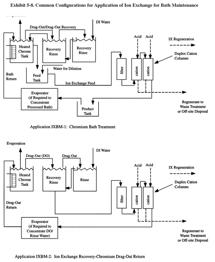
Exhibit 5-8 shows two typical applications for this technology. In IXBM-1 the ion exchange process is applied directly to the process solution and in IXBM-2 the process is applied to the return flow from the dragout recovery tank. IXBM-1 is applicable to both hexavalent chromium and trivalent chromium baths. In order for IXBM-2 to be effective, the dragout rate would have to be sufficiently high such that the percentage of the chromic acid bath treated over a given time period is sufficient to keep bath contaminants at a tolerable level. The necessary dragout rate depends heavily on the rate of contaminant buildup. Typically, a dragout rate equal to one tank volume per year will be sufficient for most hard chrome plating processes to operate with the IXBM-2 configuration. Anodizing processes and chromium plating processes with high contamination rates may require even greater dragout rates to use this configuration. When the dragout rate is insufficient (this will be evidenced by a steady buildup in contaminant concentration), the plater can bleed the bath into the dragout tank. However, this practice may overly contaminate the rinse system and result in poor rinsing.
Several respondents to the Users Survey combine the use of ion exchange with evaporative recovery operations for chromic acid recovery. In these cases, ion exchange is applied to the recovered chromic acid solution before it is concentrated by the evaporator and returned to the plating tank (PS 018, PS 082, PS 125).
Resin selectivity is an important factor with the chromic acid bath maintenance process because it reduces trivalent chromium losses. The practice of separating ions of the same charge is referred to as selective ion exchange (SIE) (ref. 46). SIE takes advantage of the preference that ion exchange resins exhibit for some ions over others to selectively separate different ions that have the same charge and would normally be removed by the same resin. Essentially, all resins exhibit selectivity. However, some resins are more selective than others and the ordering of selectivity among metal species varies among resins. When employed for chromic acid purification, the ion exchange sites of the resin exchange hydrogen for the tramp metals and Cr+3. When most of the hydrogen is displaced from the resin sites, the resin column shows its preference by displacing Cr+3 that has been attached to the resin with the preferred tramp metals. The Cr+3 goes back into solution and is returned to the bath along with the chromic acid. The process, if run to exhaustion (i.e., the point where the percentages of ions held by ion exchange sites are in proportion to the preference of the resin), will result in a high removal of the preferred tramp metals and a low removal of Cr+3 (ref. 384). If Cr+3 buildup presents a plating quality problem with a given bath, electrolysis or dummy plating (Section 5.2.2.3) can be employed.
Sulfuric acid is used to regenerate the cation exchange columns for hexavalent chromium bath applications and sulfuric acid and ammonium hydroxide (NH4OH) are used for trivalent chromium bath applications. Ammonium hydroxide is used with the trivalent application to remove copper, which is tightly held by the resin and is not sufficiently removed by the acid. The ammonium hydroxide step is not usually performed during each regeneration cycle, but rather as needed to remove the copper (e.g., every two to four times purification is performed).
Because ion exchange is a separation technique that is dependent on the general chemistry of the process solution and electrochemical differences between the metal species (i.e., plated metal vs the tramp metal), it is not applicable to the maintenance of many plating solutions. This is due to the fact that, most frequently, the metal being plated and the contaminants are both cations (e.g., nickel baths). Although different cations can be separated by selective ion exchange, it is a more difficult and less efficient process than the separation of cations and anions. In this regard, chromic acid baths are a good candidate for ion exchange since the desired species of chromium (i.e., hexavalent chromium) is an anion and the tramp metals (including trivalent chromium) are cations. Cyanide-metal complexes in cyanide plating solutions (e.g., copper cyanide) also have the opposite charge of tramp metals. However, if ion exchange bath maintenance was attempted, the cyanide-metal complex would be destroyed by the acidic conditions in the cation resin bed causing the plated metal to be removed from solution along with the tramp metals (see Section 4.4.3). Also, for these applications, ion exchange would have to compete with low current density electrolysis (dummy plating), which is an inexpensive and effective method of controlling tramp metals for many non-chromium baths.
The literature indicates that selective ion exchange (see Section 5.4.4) has been investigated as a potential
solution maintenance technology for acid etch and nickel strike baths (ref. 384). The results of the investigation
showed that the SIE process was impractical for these applications because the resin could not be adequately
regenerated. Additionally, like the cyanide-metal baths, these two baths are treatable by dummy plating, making the
SIE application less significant.
Tinker Air Force Base (Oklahoma City, OK) is conducting research, through their contractor Science Applications
Incorporated (SAIC), to evaluate the applicability of ion exchange to the maintenance of cadmium stripper solution
(ammonium nitrate). Early project results are very promising.
5.4.4 Technology/Equipment Description
This subsection contains a description of commercially available ion exchange equipment that is manufactured and/or sold by vendor survey respondents. This is intended to provide the reader with information and data on a cross section of available equipment. Mention of trade names or commercial products is not intended to constitute endorsement for use.
Eco-Tec Inc. manufactures a Decationzation Unit (DCU) that consists of a patented Recoflo™ ion exchange bed (see description in Section 4.4.1.3), filter, piping, valves and control panel. The DCU is an integrated ion exchange system as defined in Section 4.4.1.2. Depending on the model selected, the unit treats 50 to 200 gal (200 to 750 l) of chromic acid plating bath per run. The process is initiated by transferring the solution to be treated into a feed tank. The DCU is then activated and the process proceeds automatically. The unit automatically dilutes the acid to between 100 and 150 g/l (13 to 20 oz/gal) to reduce oxidation of the resin before the contaminated chromic acid passes through the bed. The DCU continuously operates a three step cycle where contaminated chromic acid is fed through the unit and the bed is rinsed and regenerated (sulfuric acid) in a counterflow direction. The treated solution is transferred to another holding tank and is returned to the bath. The surface evaporation of the bath makes up for the small quantity of water added during the process. According to Eco-Tec, the process removes 80 to 90% of the bath contaminants and generates about 3 gal/hr of residual (regenerant). The expected resin life is 6 to 12 months (ref. 385). Eco-Tec also markets a batch treatment system for treatment of the regenerant from this process.
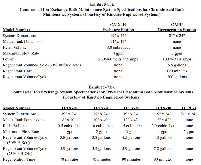
Kinetico Engineered Systems, Inc. (Kinetico) manufactures a modular ion exchange system (see definition in Section 4.4.1.3) for hexavalent and trivalent chromium bath maintenance. The modular design is referred to as "point of use" by Kinetico. The ion exchange service unit consists of a bath purification ion exchange station and an ion exchange tank. The station consists of a bath recirculation pump, cartridge filter unit, timer mechanism and controls mounted on a skid assembly. The ion exchange tank is a separate unit that connects to the service station. The service units are located at the point of use (near the plating tank) for bath treatment and the tanks are transported to a central regeneration station after use. The central regeneration station is similar in appearance to the ion exchange station, but performs the function of regeneration. The central regeneration station can be rigged to treat both hexavalent and trivalent baths. After regeneration, the tanks are returned to the point of use. Specifications for a range of Kinetico models are shown in Exhibit 5-9.
5.4.5 Costs
5.4.5.1 Capital Costs
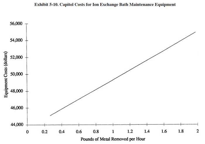
A diagram showing the equipment costs for the application of ion exchange to chromic acid baths is presented in Exhibit 5-10. Installed costs for these systems are approximately 10 to 30 percent higher than basic equipment costs.
5.4.5.2 Operating Costs
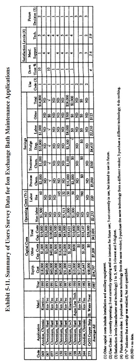
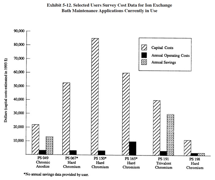
Operating cost data provided by respondents to the Users Survey are presented in Exhibit 5-11. The annual costs and savings for the respondents are shown graphically in Exhibit 5-12, which also expresses capital costs in terms of 1993 dollars. This graphic indicates that a relatively rapid capital payback is possible with this technology (see bar graph for PS 049 and PS 191).
5.4.6 Performance Experience
Eleven respondents to the Users Survey provided some detailed data on their experience using ion exchange for chromium bath maintenance. All of these applications involved hexavalent baths, except for one, which was applied to a trivalent decorative chromium bath. A summary of the Users Survey data for these applications is presented in Exhibit 5-11.
The following information and data summarize the performance experience of the eleven survey respondents.
- In general, shops using ion exchange for bath maintenance gave the technology a high rating. One exception to
the high satisfaction level was PS 244. This shop only operated the process for eight months during 1983 and
1984. Their low level of satisfaction was due to a high residuals generation rate (see Section 5.4.8). Also,
they indicated that the supplier stated capacity of the unit was 208 gallons per 12 hours and that the actual
capacity was approximately fifty percent of this rate. Another shop that gave this technology a low rating was
PS 273. This shop indicated that they discontinued use of the technology shortly after startup for
administrative and technical reasons (discussed later in this section). The one shop using ion exchange for
trivalent chromium bath maintenance had a satisfaction level of 5. The average satisfaction level for ion
exchange applied to bath maintenance is 3.9 (on a scale of 1 to 5, with 5 being most satisfactory), which is
higher than the average level rating for ion exchange chemical recovery (3.2). Seven of the shops (or 64%)
indicated that this technology satisfied the need for which it was purchased. The following is a breakdown of
the reasons why shops purchased this technology (multiple responses were permitted):
To meet of help meet effluent regulations: 4 To reduce plating chemical purchases: 8 To reduce the quantity of waste shipped off-site: 8 To reduce wastewater treatment costs: 4 To improve product quantity: 9
- The use of ion exchange for bath maintenance generally improved the production quality and to a lesser extent improved the rate of production. The following responses were provided:
Product Quality Production Rate Improved 8 4 No Change 2 6 Decreased 0 0
- Most plating shops indicated, that based on their experience with this technology, they would purchase the same type of equipment from the same vendor. The following is a breakdown of their responses:
Purchase the same technology from the same vendor: 7 Purchase the same technology from a different vendor: 1 Purchase a different technology: 3 Do nothing: 0
- One shop indicated that they are able to recycle spent chromic acid bath as another product and have therefore eliminated the need for the ion exchange system (PS 244).
- The major cost savings from the operation of ion exchange for bath maintenance were due to reductions in bath chemical use and disposal costs.
- One respondent used ion exchange to treat a chromic acid copper strip solution (PS 273). Their efforts have been unsuccessful thus far (project stopped due to change in personnel and other reasons). This facility uses, on an annual basis, 25,900 lbs/yr of chromic acid to strip approximately 3,200 lbs of copper in a 1,158 gallon strip tank. The process is operated at 160°F with a chromic acid concentration of 120 g/l. This shop purchased a water softening ion exchange unit and was told by the manufacturer's representative that they could process the bath at full strength at its operating temperature. The result was that the "copper removal efficiency dropped quickly after startup." The respondent felt that the hot, concentrated chromic acid had oxidized the resin.
- At different times, one of the respondents used ion exchange, the porous pot technology and membrane
electrolysis for chromic acid bath maintenance. This shop indicated that ion exchange provided the best results
in terms of impurity removal (PS 234). The complete statement provided by this shop, which provides a great deal
of insight to this problem, is presented in Section 5.6.6.
5.4.7 Operational and Maintenance Experience
The following summarizes the respondent's O&M experiences and provides operating labor information.
- Six shops provided operating labor data. For these shops, the average number of annual operating hours per ion exchange system were 220 hrs/yr. The labor category most frequently used for O&M was a trained technician or a wastewater treatment plant operator. The following is a breakdown of the responses for skill requirements:
Environmental Engineer: 0 Process/Chemical Engineer: 0 Chemist: 2 Consultant: 0 Plumber/Pipe Fitter: 0 Electrician: 0 Vendor: 0 Senior Level Plater: 2 Junior Level Plater: 0 Wastewater Treatment Plant Operator: 4 Trained Technician: 6 Common Labor: 0 Other: 0
- In general, the commercial equipment used for chromium bath maintenance requires little maintenance and has a relatively long equipment life. Most shops indicated that the downtime for this technology was low and none identified any major O&M problems except for PS 273.
- Long equipment life was evidenced by the fact that only one shop (PS 273) in the survey indicated that they used this process and subsequently discarded it due to deterioration (note that one shop purchased their equipment in 1983 and later sold it and that PS 244 eliminated the need for this equipment). The oldest system identified in the survey that is still operating was purchased in 1975 (PS 131). Shops estimated the life of this equipment to be between 5 and 20 years and the average estimate was 11.5 years.
- The percentage of down time for this technology was low. Nearly one-half of the respondents indicated that downtime was 1% or less.
- Several shops pointed out that there are two key technical restrictions for this technology: chromic acid concentration and temperature (PS 049, PS 150, PS 165, PS 273). Two shops indicated that the solution temperature must be 90°F or less before ion exchange treatment is performed (PS 165). Two shops pointed out that the chromic acid concentration must be below 142.5 g/l (19.0 oz/gal) CrO3 for treatment (PS 165). One respondent indicated that their operating conditions (160°F and 16 oz/gal CrO3) may have contributed to resin damage (PS 273).
- One shop indicated that elements and filters must be changed two times per year (PS 165).
- The shop operating an ion exchange unit for trivalent chromium bath maintenance reported that they experience mechanical breakdowns about four times per year. They also indicated that the downtime of their unit was less than one percent.
- PS 131, the respondent that has used this process the longest (since 1975), indicated that the process dilutes the hard chrome bath and raises the sulfate level, causing them to adjust the solution chemistry following treatment.
5.4.8 Residuals
The quantity and nature of the residuals generated from ion exchange treatment of chromium baths appears to be the most significant concern of platers using this technology (PS 198, PS 234, PS 244). The process generates a concentrated acidic waste during regeneration that contains mostly trivalent chromium and tramp cations such as iron and aluminum and dilute streams from backwashing and cleansing of the bed. Only two shops provided quantity data for this residual. PS 045 indicated that they generate 700 gallons per month from the maintenance of a 650 gallon chromic acid anodizing tank with a production rate of 363,670 amp-hrs/year. PS 244 indicated that they generated 7.7 gallons of mixed water and acid for each gallon of chromic acid anodizing solution treated.
Nearly all of the shops that reported residuals data indicated that regenerant is treated in-house and that the resultant sludge is sent off-site for disposal or recovery. One shop indicated that the regenerant is sent off-site for deepwell injection (PS 198).
It appears that a batch treatment system is the best method for processing the regenerant on-site. Shops that
attempted to treat the regenerant in their continuous treatment systems experienced overloading problems. For
example, PS 244 purchased the technology in 1983 and discontinued its use eight months later (currently recycle
chromic acid as "another product"). This shop, which has a total wastewater flow of approximately 26,000
gpd, was unable to assimilate the regenerant into their general wastewater flow. PS 244 provided the following
input: "Adds a large load to the pollution control unit. To reduce labor it needs it's own automatic pH adjust
and chrome reduction unit for it's effluent [sic]."
The need for a separate treatment system is due to the non-continuous nature of the waste stream and its high
concentration of acid and metals. The required batch treatment process consists of chromium reduction with a sulfur
compound (to reduce any hexavalent chromium present), pH adjustment (8.0 to 9.5), flocculation (polymer addition),
settling/clarification, and solids dewatering. Eco-Tec recommends the use of magnesium hydroxide for pH adjustment.
Alternatively, sodium hydroxide or lime could be used.
PS 049 generates 700 gal/mth of regenerant plus 2,300 gal/mth of other chromium wastewater. These wastes are batch treated in a 750 gal treatment tank. The wet sludge generation rate from this batch treatment process is high, 1,400 gal of sludge from the treatment of only 3,000 gal of wastewater. The high sludge production rate is due to the concentrated nature of the regenerant waste. The wet sludge is dewatered using a filter press (4,800 lbs/mth of filter cake) and the resultant filter cake is dehydrated with a sludge dryer (1,200 lbs/mth of dry sludge). The 1,200 lbs/mth of dry sludge is sent off-site for disposal. PS 049 is able to directly sewer their supernate from the batch treatment tank and the filtrate from the filter press that dewaters the sludge. Most shops will find it necessary to return the filtrate to the batch treatment process because it will contain residual concentrations of pollutants. Since much of the water from the original feed stream is contained in the filtrate, the quantity of this solution should be closely evaluated and considered when sizing the batch treatment tank.
Another residual generated by this process is spent cartridge filters. Cartridge filtration is used to prevent suspended solids from entering and fouling the ion exchange bed. No quantity data were provided by the respondents for the spent cartridge filter waste.
5.5 ACID SORPTION
5.5.1 Overview
Acid sorption is a purification technology applicable to dilute to moderately concentrated acid solutions such as anodizing and pickling baths. The term sorption, which includes both adsorbtion and absorption, is a general expression for a process in which a component moves from one phase to another, where it is accumulated, particularly for cases in which the second phase is a solid (ref. 435). Acid sorption is not a widely used technology by the metal finishing industry, although it has been commercially available in North America for approximately 15 years.
Acid sorption is one of several processes where resins are used to absorb chemicals present in surrounding solutions and the chemicals are subsequently desorbed with water. These reversible sorption processes include ion exclusion (cation resin), ion retardation (special resin), and acid retardation (anion resin). Of particular interest in metal finishing is acid retardation (ref. 340). This is a separation process where an acid is separated from its salts by using a column containing a strongly basic anion exchange resin of a specific porosity and particle size. This separation occurs because at high concentration the acid crosses the Donnan potential barrier (Donnan invasion) and is taken up by the resin, whereas the salts are excluded from it. The acid is thus "retarded" and the salts pass through the resin. This is not an ion exchange process, because the acid is desorbed from the resin with plain water.
The acid sorption or retardation process is employed to remove dissolved metal contaminants from acid baths. It is most often applied to the purification of sulfuric acid anodizing baths and sulfuric acid and hydrochloric acid pickling baths. When these solutions are contaminated with dissolved metal, the free acid concentration decreases and the anodizing or pickling efficiency drops. Additions of fresh acid are possible up to a point, but eventually, the bath must be either purified or dumped.
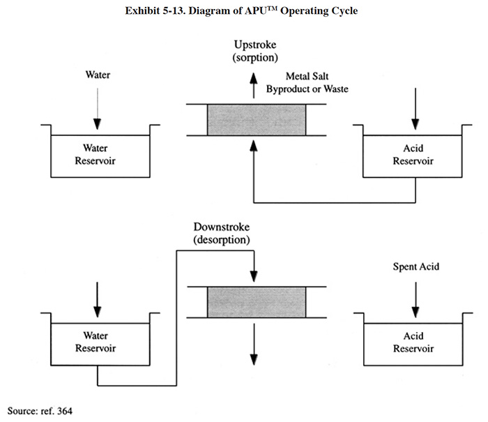
Diagrams of the acid sorption process are presented in Exhibit 5-13. These diagrams illustrate the equipment of a particular commercial acid sorption manufacturer. During the sorption step, the acid and metal salt mixture is fed up through the resin bed. Acid is sorbed into the resin while the remaining dissolved metal salts are rejected as mildly acidic solution leaving from the top of the bed. Depending on the metal salt, this solution may be waste-treated or diverted to an electrowinning cell for recovery of the metal. During the desorption step, water flows down through the resin bed. Acid is desorbed from the resin and displaced from the bottom of the bed. City water is typically adequate for this step. The resin is stable under normal operating conditions for many years without the need for regular replacement or any special treatment.
Acid sorption does not recover all of the acid in a treated bath. Rather, it recovers only a percentage (typically 80% to 90%) of the "unused" or free acid (i.e., that acid which is not chemically bonded to the dissolved metal). Typically, 40% to 70% of the total acid is free acid. Therefore, if a shop's current method of operation involves dumping and treating spent acid baths and replacing the bath with fresh solution, then acid sorption can be expected to reduce their total acid usage by approximately 30% to 65% (ref. 363, 364).
In addition to reducing acid usage there are several benefits from using acid sorption. These include: (1) reduces neutralization treatment reagent usage (e.g., caustic or lime); (2) reduces interruptions in production (i.e., when used on a continuous basis as opposed to batch purification); and (3) reduces process control variability caused by fluctuations in bath composition (i.e., when used on a continuous basis).
5.5.2 Development & Commercialization
This technology is not widely used by the plating industry and it is not well documented in most common electroplating references. Therefore, tracing its origin has been difficult. The Metals Handbook, Vol. 5 (1982) indicated that acid sorption "has recently seen extensive application in the metal finishing industry for acid recovery" (ref. 340). Examples of applications given in that reference include the purification of sulfuric, hydrochloric and nitric acids. The only manufacturer of acid sorption equipment identified during the Vendors Survey, Eco-Tec, commercialized their equipment (APU™) in 1977 (ref. 363). As of 1993, Eco-Tec has sold approximately 200 units. The APU™ was originally manufactured for the recovery of sulfuric acid anodizing solutions. However, as early as 1978 the technology was also applied to the purification of nitric acid rack stripping (nickel) baths (ref. 363).
In addition to the metal finishing industry, acid sorption is applicable to other industries that use strong acids, including the primary metals manufacturing and metals forming industries.
5.5.3 Applications and Restrictions
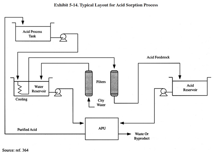
Exhibit 5-14 shows the basic configuration for acid purification using acid sorption. The process is typically performed on a continuous basis, although the same configuration could be used for batch treatment. The process is usually not performed on a batch basis because it is relatively time consuming to perform and would require that the process bath be inactive for days. For example, to purify a 2,600 gallon sulfuric acid anodizing bath from 15 g/l to 8 g/l Al would take approximately 200 hours using a resin bed with a volume of 0.42 ft3 (12 liters) (ref. Eco-Tec file).
The acid sorption technology is applicable to a range of acids and applications, including the following (ref. Eco-Tec file):
- Aluminium anodizing, using sulfuric acid
- Steel and galvanized steel pickling, using sulfuric or hydrochloric acid
- Copper and brass pickling, etching and brightening, using sulfuric or nitric acid
- Hydrometallurgical ore leach circuits
- Stainless steel and titanium pickling using nitric and hydrofluoric acids
- Electroplating rack or rework stripping, using nitric acid
- Aluminum bright dipping or electropolishing, using phosphoric and nitric acids or phosphoric and sulfuric acids
- Stainless steel electropolishing, using phosphoric and/or sulfuric acids
- Spent regenerants from acid cycle cation exchangers
- Continuously removing acid from electrowinning solutions to prevent acid interference.
Five respondents to the Users Survey indicated that they use or have used acid sorption. Their responses included the following applications: two applications for the purification of sulfuric acid anodizing solutions; one application to a hard anodize solution and two applications to hydrochloric acid pickle baths.
The five shops that use acid sorption represent 1.6% of the total number of shops responding to the Users Survey. It is interesting to note that approximately 200 acid sorption units have been sold by the only known North American manufacturer of this technology. Assuming that each of their units were sold to a different plating shop in North America, then approximately 1.5% of all North American shops have purchased this technology (based on combined EPA and Environment Canada estimates of 13,640 shops).
There are several important restrictions for acid sorption. First, the process cannot be applied to highly concentrated acids. For example, the concentration limit for nitric acid is 35% (by weight). Second, acids containing chromates should not be purified with this process. Chromates, as anions, will consume resin sites and prevent acid recovery. Third, hydrochloric acid solutions containing zinc and lead should not be purified using acid sorption. The zinc and lead form a strong chloride complex that preferably attach to the resin and prevent the sorption of acid. In these cases, it is possible to remove the zinc and lead from the acid using a process where the contaminated acid solution is passed through the resin bed two times. During the first pass, the zinc and lead chloride complex attach to the resin and are subsequently eluted with water. Then the acid would be passed through a second time to remove the acid and again be eluted with water. The key problem with this procedure is that the quantity of water needed to elude the zinc and lead chloride complex is approximately ten times greater than the quantity needed for a normal acid removal step, and therefore a large volume of metal bearing wastewater is generated.
5.5.4 Technology/Equipment Description
This subsection contains a description of commercially available acid sorption equipment that is manufactured and sold by a respondent to the Vendors Survey. This is intended to provide the reader with information and data on available equipment. Mention of trade names or commercial products is not intended to constitute endorsement for use.
The information contained in this section describes the Eco-Tec APU™, which was the only commercial acid sorption process identified during the Vendors Survey.
A standard APU™ consists of a cartridge filter, a vessel containing a resin bed, plastic piping, valving and a control system, all mounted on an epoxy coated steel frame. There are four standard APU™ sizes. Small APU™ models use hydro-pneumatic tanks to meter the flow of acid and water through the resin bed and larger units use a microprocessor-controlled flow sensor. The smallest unit has the dimensions 42 in. (107 cm) x 63 in. (160 cm) x 80 in. (204 cm) (high) and the largest unit has the dimensions 80 in. (204 cm) x 142 in. (361 cm) x 80 in. (204 cm) (high). Options include additional pre-filters, pumps, and high-temperature-resistant construction (ref. Eco-Tec file).
The operational steps of an APU™ were previously shown in Exhibit 5-13. There are two basic steps of the cycle, the upstroke and the downstroke. During the upstroke, metal-contaminated acid is pumped into the bottom of the APU™ resin bed. Acid is adsorbed by the resin bed, and the deacidfied metal salt solution, referred to as the "by-product," is collected from the top of the bed. During the downstroke, water is pumped into the top of the bed, desorbing the purified acid from the resin so that a purified acid product is collected from the bottom of the bed. The entire upstroke/downstroke cycle takes only about five minutes to complete. The equipment is fully automated to allow the cycles to repeat continuously (ref. 364). Eco-Tec has published "typical results for various applications." These are shown in Exhibit 5-15.
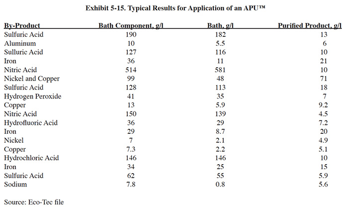
In addition to the standard APU™ components, some acid sorption installations may require cooling and additional filtration equipment. Cooling is needed when oxidizers such as nitric acid or hydrogen peroxide are present. These types of applications require cooling to approximately 90°F (32°C). Sulfuric and hydrochloric acid can be processed at temperatures up to 158°F (70°C). Eco-Tec indicated that city water is typically used for cooling and, to reduce water consumption, it can be reused for regeneration of the acid bed. Filtration is needed for most applications to minimize the pressure drop across the resin bed. The manufacturer recommends using a multimedia filter followed by a polishing cartridge filter for most applications.
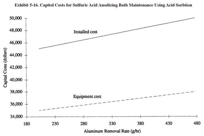
5.5.5 Costs
5.5.5.1 Capital Costs
The required size of an APU™ depends mainly on: (1) the volume of the acid bath; (2) the type and concentration of acid; (3) the dissolved metal buildup rate; and (4) the permissible operating concentration of dissolved metal. With regard to the fourth sizing criteria, most pickling applications are sized to operate at 40 g/l to 50 g/l of dissolved metal, most anodizing applications are sized to operate at 10 g/l of aluminum, and most nickel or copper stripping (nitric) applications are sized to operate at 70 g/l. Exhibit 5-16 shows the capital costs (APU™) for the maintenance of sulfuric acid anodizing baths (based on a 10 g/l aluminum feed concentration. The equipment costs include the APU™, prefiltration, feed and product tanks, and a cooling system. Installation costs are estimated to range from 10% to 35% of equipment costs. Exhibit 5-16 covers the most common range of applications. A larger APU™ unit is available that would provide 70 kg/hr of aluminum removal.
Exhibit 5-17 presents equipment costs for other applications.
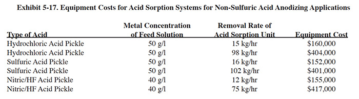
5.5.5.2 Operating Costs
The primary operating cost elements for this technology include: O&M labor, parts replacement, resin replacement and electricity. Water use costs are negligible for most applications.
Estimated operating costs for the sulfuric acid anodizing application are $16.00/kg ($7.27/lb) of aluminum removed. Operating cost data and annual savings data provided by respondents to the Users Survey are presented graphically and compared to capital costs (estimated in 1993 dollars) in Exhibit 5-18.
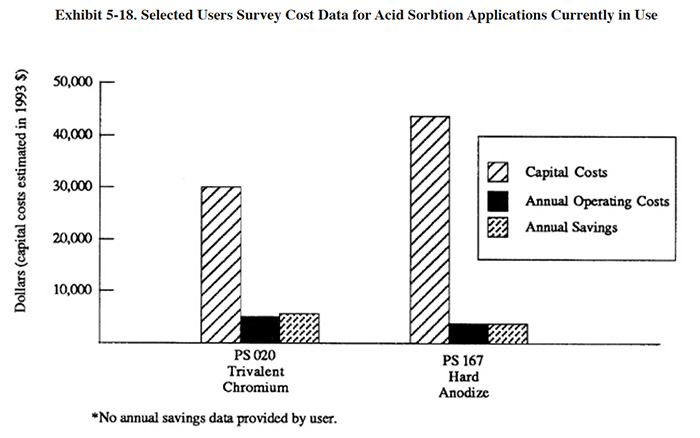
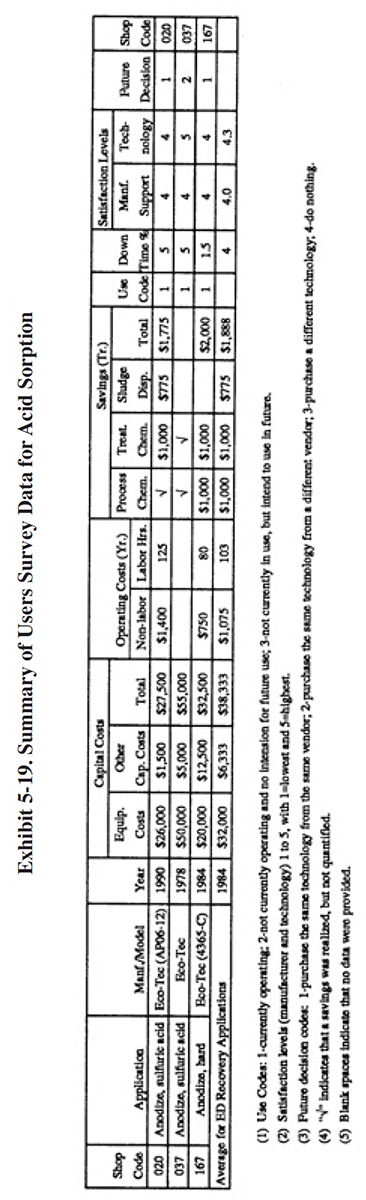
5.5.6 Performance Experience
Only three shops (PS 020, PS 037, and PS 167) completed evaluations of this technology (a total of five users were identified). A partial summary of the users data relative to acid sorption is presented in Exhibit 5-19. There are a number of observations that can be made from these data and the literature:
- All of the shops providing detailed data use the technology for sulfuric acid purification (two-sulfuric acid anodize, one-hard anodize). These three shops gave the vendor and technology high grades in terms of technical support and overall satisfaction. A11 three companies indicated that the technology satisfied the need for which it was purchased. The following is a breakdown of the reasons why the three shops purchased the technology:
To meet or help meet effluent regulations: 2 To reduce plating chemical purchases: 2 To reduce the quantity of waste shipped off-site: 2 To reduce wastewater treatment costs: 1 To improve product quantity: 3 To meet customer specification: 1
- The respondents indicated that use of acid sorption for bath purification improved product quality and in one case, improved the production rate. The following responses were provided:
Product Quality Production Rate Improved 3 1 No Change 0 0 Decreased 0 0
- Although all three shops indicated that they were satisfied with the technical support provided by the manufacturer, one shop indicated that they would use a different vendor in the future.
- The literature was also reviewed for performance experience. The only articles that were located were written by employees of the manufacturer (Eco-Tec). These include several case studies covering nitric/hydrofluoric acid and sulfuric acid pickling (ref. 364 and 365), sulfuric acid anodizing (ref. 364 and 366) and nitric acid nickel strip (ref. 363).
5.5.7 Operational and Maintenance Experience
Three shops provided operating and maintenance (O&M) information regarding acid sorption. The following summarizes the respondents O&M experience:
- The average percentage of time this technology was unavailable for use due to O&M problems (i.e., downtime) was 4%. Two shops provided comments on their O&M experience. PS 037 indicated that O&M problems were minimal and cited relay replacement as the only specific example. PS 167 stated: "Equipment is well designed, with very low maintenance and high reliability [sic]."
- All three respondents indicated that the only labor commonly needed to operate this technology was a trained technician. The average number of man-hours needed to operate this technology is 103 hrs/yr.
- All three of the respondents are still operating their acid sorption systems. One system was purchased in 1978 (PS 037), one in 1984 (PS 167) and the other system was purchased in 1990 (PS 020). It should be noted that the earlier system was purchased only one year after the technology was commercialized in North America. Oddly, although this unit has been operational for 15 years, this same respondent indicated that, if given the chance to repeat the technology selection process, they would purchase the same technology from a different vendor.
- Eco-Tec provided the following data on the expected life spans of resins for common applications of acid
sorption (species of dissolved metal is shown in parenthesis):
- Sulfuric acid (aluminum): 10 to 15 years
- Nitric/HF acids (stainless steel): 2 to 5 years
- Sulfuric acid (iron): 3 to 7 years
- Hydrochloric acid (iron): 5 to 10 years
- Nitric acid (nickel/copper): 2 to 5 years
5.5.8 Residuals Generation
The acid sorption process only recovers a portion of the free or unused acid and it does not recover any of the combined acid (salt). As a result, approximately 35 to 70 percent of the total acid used is incorporated into a by-product. The by-product or waste stream from the process will require treatment. Depending on the metal involved, treatment will range from simple neutralization (pH adjustment with caustic) to metals removal (e.g., precipitation). Eco-Tec also suggests that electrowinning can be used; however, no specific applications were identified. Sludges resulting from waste treatment will be a listed hazardous waste (F006 or F019). PS 167 indicated that treatment of their by-product results in the generation of 2 drums of sludge per year.
Eco-Tec indicates that work is currently under way to recover the by-product streams from the acid sorption system. A demonstration site has been set up for the recovery of nitric and hydrofluoric acid from the metal salt by-product, and work is proceeding on the recovery of a usable by-product from an APU™ system used with an anodizing process (ref. 364).
5.6 ION TRANSFER
5.6.1 Overview
The term ion transfer is used in this text to refer to a small group of technologies that are applied primarily to the maintenance of chromic acid baths, most notably hard and decorative chrome plating, chromic acid anodizing and chromic acid etch baths. Used for this purpose, ion transfer is a competing technology with ion exchange (cation) and membrane electrolysis. Ion transfer is also a chromium recovery technology, although it is used less frequently for this purpose. Competing technologies for chromium recovery include evaporation and ion exchange.
The basic ion transfer technology involves the use of a membrane, typically a porous ceramic pot or a polyfluorocarbon membrane (e.g., Teflon®). The unit consists of an electrolytic cell with an anode and cathode (or sets of each) that are separated by the membrane. When energized, trivalent chromium present at the anode is oxidized to hexavalent chromium, and cations (e.g., dissolved iron) present in the anolyte migrate through the membrane into the cathode compartment. The catholyte is periodically discarded and the cathode cleaned of any deposits.
As a chromium recovery technology, ion transfer equipment has been applied by survey respondents to chromium strip solutions and rinse waters. The chromium strip application uses the same equipment (porous pot) as is used for bath maintenance, but it is operated with reverse polarity. A specially designed ion transfer system for chromium recovery from rinse water was introduced in the early 1980's. Although that particular equipment (ChromeNapper) is no longer manufactured, a similar device is presently available.
5.6.2 Development and Commercialization
Chromic acid bath contamination has been a concern to platers since its development in the 1920's (ref. 367) and it
continues to be a problem today. One of the surveyed shops offered this statement:
One of the biggest problems facing hard chromium platers, such as ourselves, is the purification of the plating
baths. Contaminants in the plating tanks reduce the efficiency and quality of the chromium deposit, and once the
contaminant level reaches a certain level, the solutions must be disposed of [sic]. (ref. PS 234)
The two key problems that plague chromic acid bath users are: (1) reduction of hexavalent chromium (Cr+6) to trivalent chromium (Cr+3) causing an unwanted buildup of Cr+3 and (2) buildup of dissolved metals (ref. 368, 369 and 370). The first of these two problems can be solved using the simple process of auxiliary electrolysis or high current density dummying (Section 5.2). However, dummy plating is a relatively slow and inefficient method of oxidizing Cr+3 (ref. 370). Since production plating cannot be performed during dummy plating, the tank being treated would be unusable during this time period. Therefore, for shops using this method, dummying is usually performed during weekends.
The shortcomings of dummy plating led to investigative work by Seegmoller and Lamb in 1948 (ref. 368) involving use of the porous pot. Prior to that time, and as early as 1840, the porous pot was employed in the plating industry as a "bladder" that separated zinc anodes from gold cyanide plating solution (ref. 371). The porous pot is also mentioned in U.S. patent literature in 1918 (ref. 371). The technology, however, was not widely applied until the late 1970's and 1980's with the commercialization of the Cosmos Mineral Corporation unit (latter sold by Pfaudler Co. and subsequently by E.P. Technology) and the Hard Chrome Plating Consultants' Porous Pot (PPS1 and PPS2). Before this time period, it is believed that homemade versions of the porous pot were in use. Hard Chrome Plating Consultants indicated during the Vendors Survey that they have sold approximately 1,500 porous pot units to approximately 1,100 different plating shops.
Also, in the early 1980's, a polyfluorocarbon membrane version of the porous pot was developed (CatNapper). The polyfluorocarbon membrane acted like the ceramic pot, separating the anode and cathode reactions and products while permitting cations to migrate from the anolyte to the catholyte. The polyfluorocarbon membrane of the CatNapper is not anion or cation selective; the selectivity (i.e., migration of cations only into the catholyte) is a result of the electrical driving force. This fact distinguishes the technology from the more recently developed membrane electrolysis units that employ ion exchange membranes (Section 5.7). Another very significant difference between these technologies is that chromic acid is used as the catholyte with ion transfer technologies, whereas ion specific electrochemical membrane technology units typically use a non-chromic acid solution. This is a disadvantage of the ion transfer technologies if the catholyte, which accumulates the contaminants, is discarded. In such cases, ion transfer technologies would create a significant quantity of chrome-bearing residual. However, the use of a chromic acid catholyte would be viewed as an advantage in the event of a membrane leak. With a non-chromic acid catholyte, a membrane leak would result in significant bath contamination. The original CatNapper is no longer marketed.
It should be noted that ion exchange is a competitive technology for chromic acid bath maintenance. Ion exchange was used for this purpose as early as 1952 (ref. 368) and is still commercially available (ref. Eco-Tec file, Kinetico file). Use of ion exchange for chromic acid purification is discussed in Section 5.4.
Also, some hard chrome plating shops perform the preliminary reverse etching step (the surface of the part that is to be chrome plated is etched by reversing the normal polarity of the process tank which makes the part an anode and the lead alloy anodes become cathodes) in a dedicated etch tank. This practice reduces the introduction of iron (from the base metal) into the plating bath and delays the need to treat the bath (ref. 482).
The use of ion transfer as a chromium recovery technology probably began in the 1940's to 1950's, when the porous pot was being used for bath maintenance. However, there is no record of its use until the 1980's with the commercialization of the ChromeNapper by Innova (same manufacturer that made the CatNapper).
5.6.3 Applications and Restrictions
Exhibit 5-20 shows the two basic configurations used for application of ion transfer technologies for bath
maintenance. Configuration IT-1 shows the use of the less expensive in-tank porous pot. This unit does not have its
own rectifier, but is powered by the plating tank rectifier (alternatively, PS 118 connects to their electrocleaner
rectifier). Therefore, its use is restricted to the time period when the plating tank rectifier is energized. The
unit must be removed from the tank during idle periods, otherwise the contaminates will migrate from the catholyte
back into the bath. One of the survey respondents indicated that they remove the unit from the tank whenever it is
idle for more than 8 hours (PS 118).
Configuration IT-2 shows an external unit that is powered by its own rectifier. Either the multi-pot porous pot unit
or the external polyfluorocarbon membrane unit would be used in this manner. Plating solution is pumped into the
tank containing the cells, circulated and returned by gravity to the plating bath.
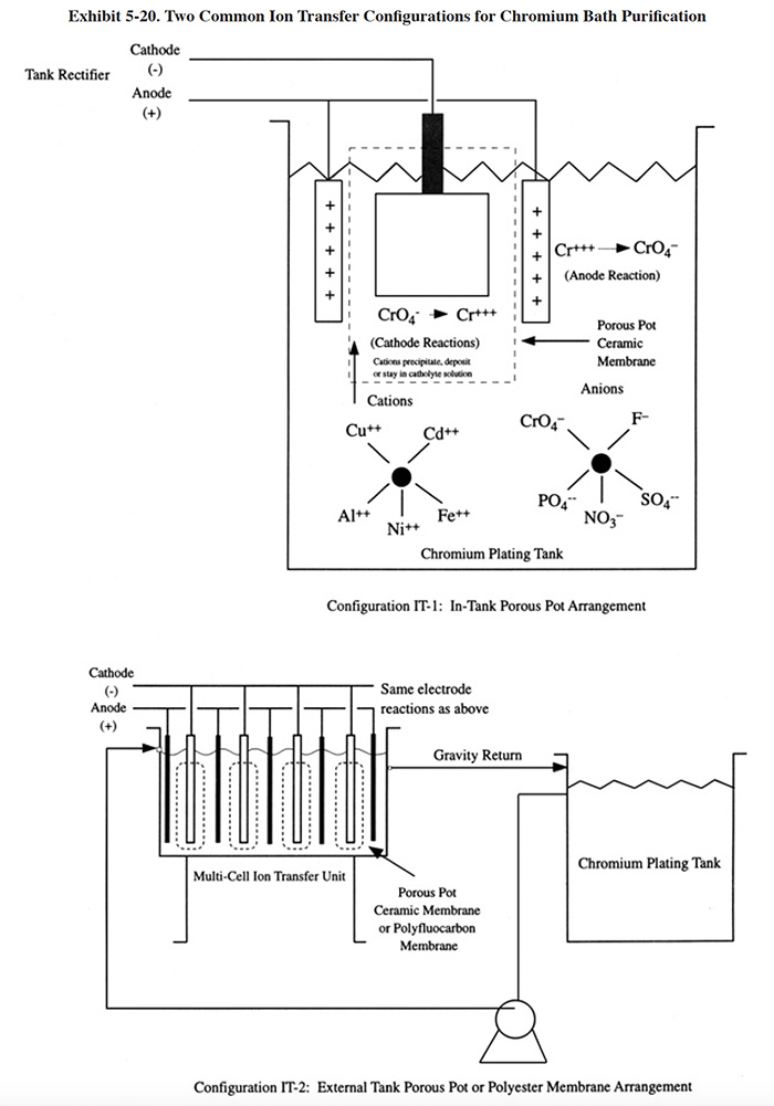
Although the ion transfer technology has its roots in non-chromium applications, and one reference indicated that other applications are possible (ref. 371), no non-chromium applications were found during the course of the NCMS project. The specific applications that were identified were all for chromic acid solutions except for one application to caustic chromium strip. The chromic acid applications include hard chromium plating (single and dual catalyst), decorative chromium plating (single and dual catalyst), chromic acid anodizing and chromic acid etch.
Two important restrictions should be noted for the ion transfer technology. First, this technology should be considered as a bath maintenance method and not a means of quickly rejuvenating a spent bath. Chromic acid baths that are laden with dissolved metal contaminants will take months to correct with ion transfer and a significant volume of chromium waste can be generated in the process. The correct application of this technology is as a continuous maintenance method that is first applied before the bath is overly contaminated. Second, the ion transfer technology is not practical as a bath maintenance method where the desired tramp metal contamination level (excluding consideration of Cr+3) is less than 4 g/l. To reach a lower point would require frequent changes of the catholyte solution, resulting in a very high waste volume.
Exhibit 5-21 shows the basic configuration (IT-3) used for application of ion transfer for chromium recovery from rinse water. The IT-3 configuration takes advantage of the significant amount of surface evaporation that normally occurs in chromium plating baths operating between 115°F and 140°F. By using countercurrent recycle of rinse water through multiple-rinse tanks and a chromium recovery unit on the final rinse, the chromium plating process becomes a closed-loop operation. Chromic acid is removed from the rinse water and concentrated into the ion transfer system modules where it can reach a concentration of approximately 150 g/l. The recovered chromic acid is periodically drained from the ion transfer system modules and transferred to the plating bath (ref. 39).
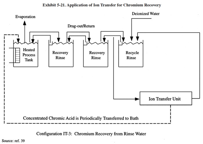
Exhibit 5-22 presents vendor supplied data that shows the performance of an ion transfer unit (APS-3, see specifications in Section 5.6.4) applied to a decorative chromic acid plating bath (ref. i3 file). During the data collection period, the unit was operated at 110 amps and 6.5 volts. The data indicate there is an average removal rate of 385 grams of cations (copper, nickel and zinc) per day (0.85 lbs/day) when the bath (6,018 l) is treated from a concentration of 12.2 g/l to 10.6 g/l.
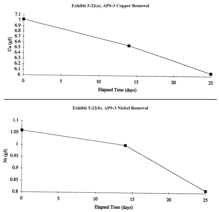
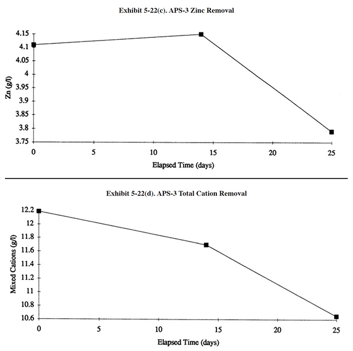
The PPS1 or the PPS2 can also be used as a chromium recovery device when placed into a caustic strip solution and reverse polarity is applied. Chromic acid will accumulate within the ceramic pot and is periodically removed and transferred to the plating bath. One of the survey respondents used the equipment in this way and reported that it was the best application for this equipment (i.e., they also tried using the PPS1 as a bath maintenance technique) (ref. PS 006).
5.6.4 Technology/Equipment Description
This subsection contains a description of commercially available ion transfer equipment that is manufactured and/or sold by respondents to the Vendors Survey. This is intended to provide the reader with information and data on a cross section of available equipment. Mention of trade names or commercial products is not intended to constitute endorsement for use.
The PPS1 and PPS2 (Hard Chrome Plating Consultants) are the simplest commercial versions of the ion transfer technology. Both units are single cell systems, the difference being their size and capacity. The PPS1 is the larger of the two units and is recommended by the manufacturer for tanks containing up to 3,000 gal. of chromium plating solution. The PPS2 is recommended by the manufacturer for shops with less than 700 gal. of plating solution. Each unit consists of a porous pot, anode, cathode and connecting bars. The pots have a 40% porosity and a pore size of 1 micron or less. The cathode is made from lead alloy mesh (ref. 371). These units are designed for use with the 2-bus bar, reversible rack plating tank configuration. However, they can be rigged for other bus bar configurations. The units are located directly in the plating tank during use, where they consume approximately six to twelve inches of tank length and have a maximum working depth of 25 inches. No pumps, piping or power supplies are usually needed to operate the unit. The porous pot is powered by the tank rectifier. The manufacturer also sells a PPS-4 unit that is applicable to cadmium, nickel copper and other solutions.
Before using the PPS1 or PPS2, the porous pot is filled with plating solution or fresh chromic acid solution, without catalyst (approximately 2 gallon for the PPS1). The unit is then lowered into the plating bath. By design, the lip of the pot is above the solution level of the plating tank to avoid having direct exchange of solution. When the unit is energized (smaller unit draws about 70 amps and the larger unit 210 amps) (ref. 371), Cr+3 in the anolyte (plating tank) is oxidized to Cr+6 and cations in the anolyte are electrically driven through the pores of the pot into the catholyte. Some cations are deposited on the cathode, most remain in solution. It is unclear whether the cations are electrolytically deposited or precipitated. One source suggested the latter method of deposition occurs because hydrogen evolution is occurring at the cathode which will result in a rise in pH (ref. 371). The chrome present in the catholyte is reduced to Cr+3. As these changes occur, the effectiveness of the unit diminishes and eventually the catholyte is replaced. The frequency of catholyte replacement is usually in the range of 8 hours to 3 days (ref. 370).
The E.P. Technology unit (patent formally owned by Cosmos Minerals Corporation and subsequently by Pfaudler Co. and later by E.P. Technology) consists of a tank holding four to eight pots and an equal number of sets of anodes and cathodes. Basically, this is the same technology as the Hard Chrome Plating Consultants PPS1 or PPS2, but on a much larger scale. The pots hold the catholyte solution and cathode. Plating solution is pumped to the tank on a continuous basis; it circulates around the pots and is returned by gravity flow to the plating tank. The cells are powered by a rectifier (1,000 to 2,000 amps depending on the number of pots) dedicated to the purification unit. The unit requires lateral exhaust ventilation similar to a chrome plating tank, since chromic acid mist is generated by the release of oxygen at the anode and hydrogen at the cathode. It is not known if the EP Technology unit is still marketed. No recent advertising or installations were located during this project.
Artec manufactures four models of the polyfluorocarbon membrane ion transfer technology for chromium bath maintenance (APS series) and seven models for chromium recovery from rinse water (ARS series) (marketed by i3). Three of the APS models are progressively larger units of similar design (Exhibit 5-23) and the fourth is a Unicell model. The three larger Artec units operate in a manner very similar to the EP Technology porous pot unit. Solution is pumped from the plating tank to the unit, circulated past the cells and returns by gravity to the plating tank. Within the unit, the chromic acid solution circulates around modules (3 to 12), which extract cationic impurities. The solution collected in the membrane compartment which contains iron, trivalent chromium, and other cation impurities is discharged to waste treatment. System specifications for the Artec units are given in Exhibit 5-24. The Artec Unicell is a single module unit that fits into a plating tank, and therefore functions like the single porous pot cell units.
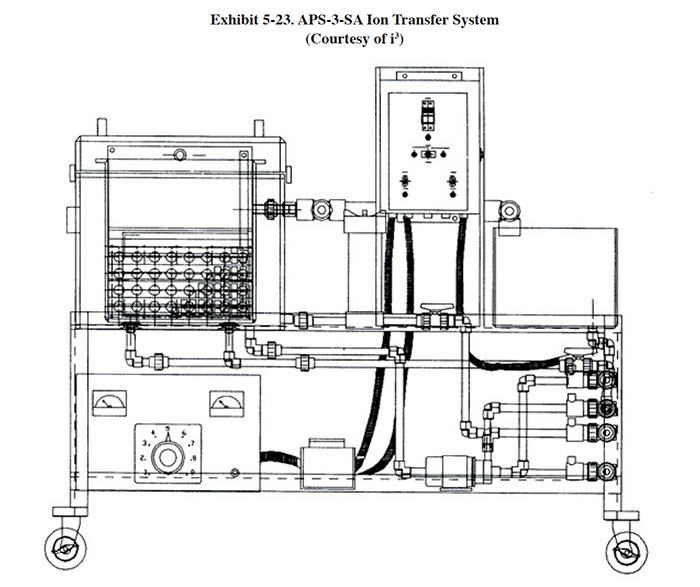
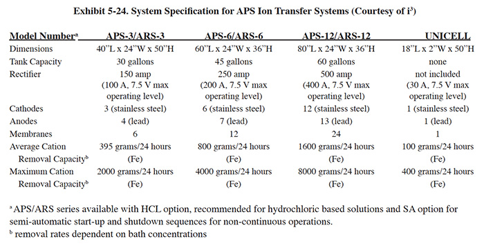
5.6.5 Costs
5.6.5.1 Capital Costs
The PPS1 and PPS2 are sold for $800 and $460, respectively. The capacity of these units is not documented, so no attempt has been made in this report to show capital costs over a range of removal capacities. The manufacturer suggests that the PPS2 is applicable to tank volumes of 700 gallons or less and the PPS1 should be used for higher volumes, up to approximately 3,000 gal. (ref. Hard Chrome Plating Consultants, Inc. file)
The capital costs for the Artec polyfluorocarbon membrane technology ranges from approximately $10,000 to $30,000 for standard units with larger custom units available.
5.6.5.2 Operating Costs
Operating costs for the Artec polyfluorocarbon membrane technology are estimated by the manufacturer to range from $5 to $27 per pound of iron removed, depending on the level of bath contamination.
Respondents to the Users Survey reported that O&M labor requirements for the porous pot (PPS1 and PPS2) range from 26 hr/yr to 260 hr/yr and that non-labor costs range from $100/yr to $500 (excluding anolyte disposal costs).
Selected Users Survey cost data for the ion transfer technology is presented in Exhibit 5-25.
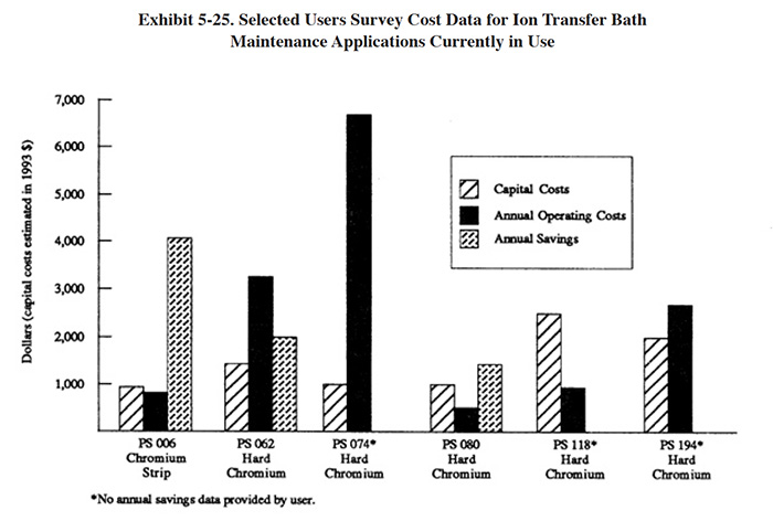
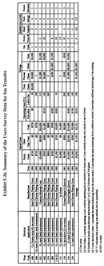
5.6.6 Performance Experience
A partial summary of the Users Survey data relative to ion transfer technology is presented in Exhibit 5-26. There are a number of observations that can be made from these data, other data contained in the database and from the literature.
- In general, shops using ion transfer for chromic acid bath maintenance gave the technology a high rating. The average satisfaction level for ion transfer applied to bath maintenance is 3.8 (on a scale of 1 to 5, with 5 being most satisfactory). Seventy percent of the shops indicated that this technology satisfied the need for which it was purchased. The following is a breakdown of the reasons why shops purchased this technology:
To meet of help meet effluent regulations: 2 To reduce plating chemical purchases: 8 To reduce the quantity of waste shipped off-site: 2 To reduce wastewater treatment costs: 1 To improve product quantity: 5
- The use of ion transfer for bath maintenance generally improved the production quality but did not impact the rate of production. The following responses were provided:
Product Quality Production Rate Improved 6 2 No Change 2 4 Decreased 0 1
- Most plating shops indicated that, based on their experience with this technology, they would purchase the same type of equipment from the same vendor. The following is a breakdown of their responses:
Purchase the same technology from the same vendor: 8 Purchase the same technology from a different vendor: 1 Purchase a different technology: 2 Do nothing: 0
- The major savings from the operation of ion transfer for bath maintenance was the result of reductions in bath chemical use. The reported savings were in the range of $500 to $2,000 per year.
- The ion transfer process is relatively slow with respect to removal of dissolved metals. For example, a PPS2 was tested on a 50 gal solution of chromic acid contaminated with 13.05 g/1 of copper, iron and nickel (i.e., combined concentration). The contaminant level was decreased to 4.08 g/1 in 192 hours (8 days). The maximum tank volume applicable to the PPS2 is 700 gal (ref. 371). For this size tank the time needed for purification would be 112 days. If the tank were used for production while purification was conducted, the time for purification could be much longer and possibly unachievable (e.g., if the introduction rate of contaminants exceeded the removal rate).
One survey respondent has used three different types of chromic acid bath maintenance techniques since 1980 (ref. PS 234). This shop did not provide the data requested in the survey form, but attached the following useful insight:
Over the years, we have tried three different technologies in order to solve this problem. We moved into new offices 2 years ago, and I have been unable to locate my files relating to the specifics of each system. Therefore, the following information is based on my recollection.
- Short-bed ion exchange. Purchased from EcoTec (Canada) in 1983 - 1985 at a cost of $ 17,000 plus. Of the three systems, this technology provided the best results as far as removing impurities. The major problem, which resulted in our selling the equipment, was the overloading of our waste treatment facilities with hex chrome - producing large quantities of F006 sludge.
- Porous Pot. Purchased from Cosmos (California) somewhere around 1980 - 1981. Purchase price unknown. This experiment was a disaster. The cleaning of the system was an incredibly messy operation which took 4 to 5 hours to complete. This system also produced abundant amounts of hex cr. waste, and the porous pots were susceptible to breakage. This system gave only marginal results for purification of the bath, although it did a good job of removing trivalent chromium.
- Membrane. Unable to recall name of company. They were out of the Atlanta, GA area. The cost of the unit was around $8,000. This system was similar to the porous pot technology with the substitution of a membrane for the porous pots. Like its predecessor, however, it was dreadful to clean out the collected material. It also generated tremendous amounts of hex cr. and seemed limited to the removal trivalent chromium only. The other impurities such as cu. and iron were largely unaffected.
All of these systems were sold, and we are in the market for suitable (proven) technology [sic].
[The third technology discussed by the respondent was actually a membrane electrolysis technology (Section 5.7). The particular system they purchased is no longer being sold. As indicated in Section 5.7, some membrane electrolysis technology applications have been successful.]
- There was very little performance experience documented in the survey forms with respect to the polyfluorocarbon membrane units. Of the two shops providing data, one was satisfied with its performance, but discontinued its use due to maintenance problems (PS 134) and the other respondent was dissatisfied with the performance of the unit (PS 194).
5.6.7 Operational and Maintenance Experience
The following summarizes the respondent's O&M experiences and provides operating labor information.
- The average number of labor hours for ion transfer usage was: 148 hrs/yr. The skill category most commonly needed for operating this technology is a plater or common labor. The following is a breakdown of the responses for skill requirements:
Environmental Engineer: 0 Process/Chemical Engineer: 0 Chemist: 0 Consultant: 0 Plumber/Pipe Fitter: 0 Electrician: 0 Vendor: 0 Senior Level Plater: 4 Junior Level Plater: 3 Wastewater Treatment Plant Operator: 1 Trained Technician: 2 Common Labor: 3 Other: 0
- In general, the commercial ion transfer equipment used for chromium bath maintenance requires little maintenance, has a relatively small downtime and a relatively long equipment life.
- The porous pot technology is free of complex mechanical operational and maintenance problems due to its simple
design and lack of moving parts. For the in-tank units, the following O&M items were identified by survey
respondents:
- Liquid and sludge must be removed from the pots periodically (range of frequency was 1 day to 1 week) (ref. PS 006, PS 062, PS 194, PS 074, PS 080, PS 1 18).
- Unit must be dismantled and cleaned every week (PS 021).
- The ceramic pots are fragile and/or must be periodically replaced due to breakage (PS 006, PS 062).
- The unit must be removed from the tank during idle plating times and/or it is difficult to move from tank to tank (PS 062, PS 118).
- Requires frequent observation to assure proper operation (PS 006).
- Use of technology causes catalysts to become unbalanced (PS 006).
- Unit consumes plating tank space (PS 062).
- Only one of the respondents to the Users Survey used a multiple-porous pot unit. This respondent reported pot breakage to be an O&M problem. Similar experience is found in the literature (ref. 372).
- Users of the polyfluorocarbon membrane units for bath maintenance and chromium recovery reported that equipment replacement was frequently necessary and expensive (PS 194, PS 134).
5.6.6 Residuals Generation
Due to a lack of data, the true pollution prevention value of the ion transfer technology cannot be fully ascertained. Some evidence indicates that the porous pot technology is inefficient in the sense that a significant quantity of chromium waste is often generated relative to the volume of bath being maintained. This observation is especially evident for the large-scale porous pot units (i.e., Cosmos Minerals Corporation, Pfaudler, EP Technology). For example, a report prepared for the Air Force described an application where 16,830 gal. of hard chromium plating bath was maintained with two large porous pot systems (8 pots each). Annually, these systems generated 10,000 gallon of chromic acid waste. Also, equipment replacement (electrodes, pots) costs were $60,000 annually (ref. 372).
Similarly, one survey respondent indicated that use of a PPS1 generated 4,800 gpy of waste (combination of catholyte and wash-down water that is sent off-site for recycle) while maintaining a 3,000 gal. bath (PS 074).
For these applications, it appears that a "bleed and feed" strategy would be more efficient than use of a porous pot. However, some other survey respondents reported less waste generation and in some cases very small volumes (e.g., PS 194 and PS 118).
No data were located with respect to the waste generation rates of the polyfluorocarbon membrane technology.
5.7 MEMBRANE ELECTROLYSIS
5.7.1 Overview
This group of bath maintenance technologies was used by 5 (or 1.6%) of the respondents to the Users Survey. These technologies, applied primarily to the maintenance of chromic acid solutions such as decorative and hard chrome plating baths, chromic acid etch solutions and chromic acid anodizing baths, compete with ion exchange (Section 5.4) and ion transfer (Section 5.6) technologies. All of the applications identified in the Users Survey involve these solutions. Membrane electrolysis is also applicable to non-chromium solutions, including those formulated with sulfuric acid and sodium hydroxide, but are less frequently used for them.
Membrane electrolysis is related to the ion transfer technology discussed in Section 5.6, however, commercial membrane electrolysis units employ ion specific membranes rather than the ceramic or polyfluorocarbon materials used in ion transfer.
With membrane electrolysis, an electrical current is passed through electrolytes that are separated by an ion specific membrane. Two reactions typically occur as the result of using membrane electrolysis: (1) ions of a given species are electrically driven across a selective membrane and (2) chemical changes occur (e.g., oxidation/reduction such as the electro-oxidation of Cr+3 to Cr+6) at the electrodes.
The term membrane electrolysis is found in German literature (membran-elektrolyse) (ref. 520). Some U.S. manufacturers of this technology prefer to categorize their equipment as an electrodialysis technology. This latter term however, is more often reserved for an electrochemical device with alternating anion- and cation-exchange membranes (referred to as stacks) that alter the concentration and/or composition of an electrolyte simply as the result of electromigration (ref. 401, 423).
The primary function of membrane electrolysis, when applied as a bath maintenance technology, is to lower or maintain at an acceptable level the concentration of metallic impurities in plating, anodizing, etching, stripping and other metal finishing solutions. This is accomplished through the use of an ion exchange membrane(s) and an electrical potential applied across the membrane(s). The membranes employed with these technologies are ion-permeable and selective, permitting ions of a given electrical charge to pass through. Cation membranes allow only cations, such as copper, nickel, and aluminum to pass from one electrolyte to another, while anion membranes allow only anions, such as sulfates, chromates, chlorides, or cyanide to pass through. Bath maintenance units can be configured with only cation or anion membranes or both. The oxidation of Cr+3 to Cr+6 occurs at the anode, in the same manner as high current density dummy plating described in Section 5.2.2.3. The anode material and/or coating must be properly selected in order for this reaction to occur.
The most common applications for this technology within the plating industry are the purification of chromium plating (especially hard chromium) and chromic acid anodizing baths. These baths become contaminated with various metallic impurities that are introduced mostly as a result of: drag-in; anodic etching; corrosion of electrodes, bus bars, racks, fixtures and parts; and reduction. The metal impurities combine with the acid in the bath and form metal salts. Eventually, the concentration of metallic impurities exceeds operational limits and the baths must be discarded.
Hard chromium plating solutions are most often fouled by iron, aluminum, copper and trivalent chromium. Iron is contributed during the anodic etch of steel parts, which is usually performed in the plating bath prior to plating. Etching prepares the surface of the parts and improves adhesion. Iron is also contributed by the corrosion of steel parts that have been dropped in the tank and not retrieved. Aluminum is contributed to hard chromium baths mostly from aluminum fixtures that hold the parts during plating. Some facilities chromium plate aluminum parts, which also contributes aluminum to the bath. Copper is added mostly from corrosion of copper bus bars and fixtures. Trivalent chromium is generated in chromium plating baths when hexavalent chromium (i.e., the desired chromium species) is reduced. This occurs partly due to the introduction of organic chemicals to the bath, but is mostly due to an imbalance in the plating process. During plating, hexavalent chromium is reduced to chromium metal on the surface of the part (cathode). However, some hexavalent chromium is incompletely reduced to trivalent chromium. Simultaneously, trivalent chromium is oxidized at the anode to hexavalent chromium. An imbalance is created when the surface area of the plated part approaches or exceeds the surface area of the anode. This condition is most prevalent with inside diameter (ID) plating since the anode, which is inserted into the part, must be physically smaller than the part.
The deleterious effect of metallic impurities on the chromium plating process is widely acknowledged, but the tolerable limits are often debated. Metallic impurities are known to limit the permissible cathode current density, resulting in slower plating to obtain comparable deposit quality (ref. 369). Various defects in chromium plated deposits, including burning, roughness, pitting, and reduced adhesion, brightness and hardness are also attributed to metallic impurities. The actual effects of metallic impurities depends on many factors including the overall chemistry of the bath, plating procedures used and the type of parts being plated (ref. 370).
Various control limits for chromium plating baths are in use, with a 4 g/l combined concentration of iron, aluminum and copper, and other tramp metals as a common standard. Experts are in less agreement over trivalent chromium control limits and many report advantages from the presence of some Cr+3. However, a 4 g/l control limit for Cr+3 is typical of that used in industry (ref. 370).
The effects of metallic impurities on chromic acid anodizing baths and acceptable limits are not as well documented as hard chromium plating. The key metallic impurities are trivalent chromium and aluminum. Trivalent chromium is generated by the same methods discussed for hard chromium plating (i.e., introduction of organics and excessive cathode area in relation to anode area). One widely recognized source recommends controlling Cr3 below 3 g/l to prevent darkening of the anodic film. A 4 g/l limit is used by the Air Force (ref. 384).
Aluminum is added to the bath by the electrolytic etching of the parts during the process (in anodizing, the part is the anode) and causes reduced efficiency. Chromic acid in the anodizing bath is neutralized by aluminum dissolving in the solution. Knowing the neutralizing effect of aluminum, the baths are typically controlled by pH rather than direct aluminum concentration. This practice is implemented by the Air Force, where the upper control limit is pH 0.85 (ref. 384). In practice, a new chromic acid anodizing bath is formulated by the Air Force with 48 g/l of chromic acid. The control limits for chromic acid are 40 to 105 g/l. As chromic acid is neutralized by dissolving aluminum, chromic acid additions are made to keep the pH below 0.85. These additions increase the chromic acid concentration of the bath. In theory, once the bath reaches a chromic acid concentration of 105 g/l, the bath is discarded. However, more frequently, the pH of the bath becomes difficult to control at approximately 75 g/l of chromic acid and it is discarded (ref. 384).
5.7.2 Development & Commercialization
Membrane electrolysis is the most recent technology applied to the maintenance or purification of plating baths. Although the membrane electro-transport phenomenon was observed in the 1800's, it did not achieve any commercial application until durable, ion-selective membranes were developed in the 1950's. The first applications were for desalination of brackish water using electrodialysis. In the mid 1970's, the first attempts in the U.S. were made to use electrodialysis to reclaim plating chemicals from rinse solutions. The earliest commercial success was the recovery of nickel. The implementation of membrane electrolysis for bath purification proceeded less quickly due to operational problems with membrane fouling and electrode maintenance. Early work on bath maintenance was performed by the U.S. Bureau of Mines for rejuvenation of spent chromic acid pickling solution in the late 1970's. The Bureau built an industrial scale unit using Du Pont's Nafion® ion exchange membrane and a sulfuric acid catholyte and tested it at several plating shops in the mid-west in 1979 and 1980. A commercial unit (COPS), based on the Bureau of Mines concept and design was developed and applied to a sodium dichromate/sulfuric acid pickle for brass forgings and a chromic/sulfuric acid copper strip solution (following carburization) (ref. 389). The use of membrane electrolysis for plating bath maintenance did not accelerate until the mid-1980s when a second generation of technology, also using the Nafion® membrane, was introduced for the purification of hard chromium plating baths (ref. 370). That system (Ionsep) uses a patented approach employing a caustic catholyte solution, rather than sulfuric acid, to precipitate the tramp metals as they cross the membrane. Also, during the early 1980's, commercial efforts were also directed at an ion transfer technology using a non-selective polyfluorocarbon membrane (CatNapper) (see Section 5.6). A French company manufactured a membrane electrolysis unit that was marketed in the U.S. in the mid- to late-1980's (marketed by Pentol Incorporated USA). That system was previously applied to chromic acid anodizing baths by aerospace firms in France (ref. 390). Other plating bath and pickling solution applications of membrane electrolysis including non-chromium applications, have since been commercially proven. Increased commercial activity in membrane electrolysis was spurred by cost increases for chemicals and waste disposal and environmental laws such as the requirements in the Resource Conservation and Recovery Act (RCRA) for waste minimization. These considerations have urged plating shops to search for methods of reducing the disposal frequency of process solutions.
5.7.3 Applications and Restrictions
Potential applications of this technology for plating shops are shown in Exhibit 5-27. Application ME-1 is the typical bath purification scheme and the most widely used application for this technology. Application ME-2 shows the use of this process for several functions related to bath maintenance and chromic acid recovery.
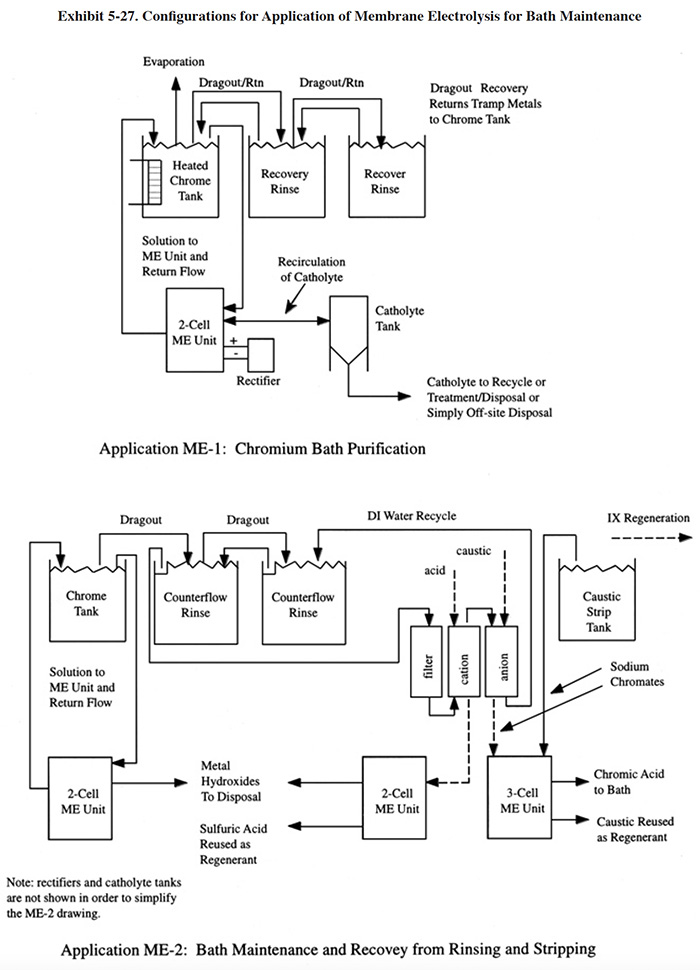
The bath maintenance process in ME-1 is typically operated on a continuous basis. Process solution is pumped to a tank holding the electrolytic cell (alternatively the cell can be placed into the process tank) or through a stacked membrane system and returned to the bath. With each pass of the process solution, a portion of the cations are transported through the membrane and into the catholyte solution. This application describes the use of membrane electrolysis systems that operate with either an acidic or caustic catholyte (see catholyte discussion in Section 5.7.4).
Application ME-2 is a theoretical configuration showing: (1) conventional bath maintenance; (2) reformulation of cation regenerant; and (3) reformulation of a combined anion regenerant/caustic strip solution. The first two applications use the two cell membrane electrolysis configuration (one anode located in an anolyte and one cathode located in a catholyte) and the third uses a more complicated three cell arrangement (anode, reactor and cathode compartments). With this particular application of a three cell arrangement, sodium dichromate solution is reformulated into sodium hydroxide and chromic acid. Other applications requiring three compartments include phosphoric acid and conversion coating bath purification (ref. 384).
The functions of the two and three compartment cells are described in Exhibit 5-28. With the two cell arrangement, the chromic acid bath is the anolyte and the tramp metals present in that solution are transported into the catholyte, where they precipitate as metal hydroxides. With the three compartment cell, the anolyte is the sodium dichromate solution. The cations in the anolyte are transported into the center compartment (reactor compartment) where the multi-valent cations are precipitated as metal hydroxides. The mono-valent cations are further transported to the cathode compartment where the caustic is reformed. This process, which includes the precipitation of metals, is patented by Ionsep.
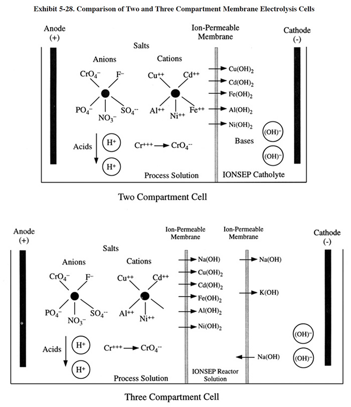
For the plating industry, membrane electrolysis is most applicable to the maintenance of chromic acid solutions, including hard chromium and decorative chromium plating, chromic acid etching, chromic acid anodizing and chromic acid stripping (e.g., copper). These are the only applications that were identified during the NCMS/NAMF Users Survey. Other potential applications include sulfuric and nitric acid and sodium hydroxide based solutions (e.g., pickle, etch, strip, rust removal), chromate conversion coating, and sodium dichromate deoxidizer (ref. 384).
5.7.4 Technology/Equipment Description
5.7.4.1 General
Membrane electrolysis is the newest of the chromium bath purification technologies. In the most basic sense, these units consist of: (1) a tank containing an anode and cathode compartment separated by a selective membrane(s), and (2) a power source. The membranes are ion specific in a manner similar to ion exchange resin. They allow the passage of only positive or negative ions, depending on the type of membrane. This design element is used in this text to distinguish these units from ion transfer technologies that employ non-ion permeable membranes such as ceramic pots or a polyfluorocarbon material (Section 5.6). Cation specific membranes are used for chromic acid purification, the most common application for this technology. When current is applied to the cell, cations present in the anolyte flow through the cation permeable membrane. The anions in the catholyte are restricted by the membrane and remain in that compartment. Trivalent chromium present in the anolyte (plating bath) is reoxidized to the hexavalent state. Membrane electrolysis units can be configured with only cation or anion membranes or both.
It is important to note that Cr+3 is a cation, while Cr+6 combines with oxygen in solution to form CrO4 and acts like an anion. Therefore, in a membrane electrolysis system, the Cr+3 that is not oxidized to Cr+6 will behave like iron and aluminum ions and be transported through the cation membrane while the Cr+6 remains in the plating solution. The loss of Cr+3 in this manner is undesirable since Cr+3 can be restored to a useful state by simple oxidation at the anode.
Further, the catholyte solution, into which the cations are transported, becomes more quickly spent when Cr+3 passes through the membrane. The cathode solution is subsequently discarded and its chromium content will increase disposal costs. Therefore, units with a rapid Cr+3 oxidation rate will generate less process residual and the residual will have a lower chromium content.
The available commercial membrane electrolysis units are discussed in Section 5.7.3.1. Four different membrane electrolysis manufacturers were identified during the literature search, Users Survey and Vendors Survey. A comparison of these technologies shows that there are several basic variations among the units. The following discussion highlights these differences.
The choice of catholyte solution is one major difference between the various commercially available units. Most of the units use mineral acid (typically sulfuric acid) as the catholyte, which was used by the Bureau of Mines in their early work. With an acidic catholyte solution, cations flow through the permeable membrane and into the acidic catholyte. The electroplatable cations deposit on the cathode and the non-electroplatable cations stay in that solution as salts. Periodically, the cathode is cleaned and the catholyte solution is discarded and replaced (370).
One of the available technologies uses a patented caustic catholyte (combination of alkali reagents). The caustic catholyte causes the precipitation of cations as they pass through the membrane. This overcomes any problem of plating-out the cations on the cathode. This catholyte converts multi-valent metal cations entering the catholyte solution into insoluble hydroxides. The hydroxyl ions needed to react with the metal cations are formed at the cathode of the cell. Precipitation of the cations prevents a loss of conductivity and eliminates the buildup of a deposit on the cathode; consequently, the operational period is extended to two or more weeks and there is no need to clean the cathode.
The overall appearance of the commercially available units varies significantly. Some of the units are configured similarly to the Bureau of Mines' prototype units. The chromic acid bath is pumped to a tank on either a batch or continuous basis. The tank contains multiple cathode cells, around which the anolyte (chromic acid bath) is circulated. Another commercial unit has a conventional electrodialysis design with "stacks" of membranes that are kept together in a clamping unit which looks similar to a filter press. Anode and cathode electrodes are located at opposite ends of the stack. The plating solution is pumped through the stack. The pumps and other support equipment are located on a skid. A third configuration, places the cathode in a "membrane sock," which is lowered into the plating tank. The catholyte is circulated from a side tank into the cathode compartment (ref. 384).
The capacities and capabilities of membrane electrolysis units should be measured in terms of the tramp metal removal rate (g/hr), which will vary over a range of tramp metal concentrations in the anolyte. Unfortunately, there is a limited amount of such data available. Exhibit 5-29 shows the results of a comparative test of a caustic catholyte membrane electrolysis system and a single cell porous pot unit.
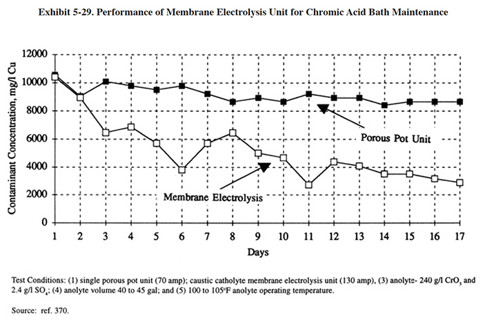
5.7.4.2 Commercially Available Equipment
This subsection contains a description of commercially available ion specific electrochemical membrane technology equipment. This is intended to provide the reader with information and data on a cross section of available equipment. Mention of trade names or commercial products is not intended to constitute endorsement for use.
Ionsep Corporation has manufactured electrochemical processing equipment since 1985 and has sold more than 150 units to metal finishing firms. Approximately two-thirds of their units were sold for chromic acid applications. The basic Ionsep unit consists of a electrolytic cell, a catholyte tank (located near and plumbed into the electrolytic cell ), and a power source (typically a 500 amp rectifier). The cell is inserted in a protective 6 to 9 in. diameter PVC pipe approximately 36 in. long that is kept in the plating bath during operation (alternatively, a side tank is used, especially with larger applications). The pipe is perforated to permit plating solution to enter and flow around the cell membrane. Within the PVC pipe is a cylindrical shaped anode, which is exposed to the plating bath, and a selective membrane "sock" that creates an inner cathode compartment. A cathode and catholyte solution (an alkaline solution) are located in the sock. This configuration is termed a two compartment cell where the anode compartment is the plating bath and the cathode compartment is the space inside the sock.
In operation, a direct current is passed to the cell electrodes and the catholyte is continuously circulated from the catholyte tank (typically a 55-gal. plastic drum with a small circulation pump located on top) into the sock formed by the membrane. The cations (e.g., iron) are electrically driven from the plating bath through the selective membrane and into the cathode compartment. The metal cations precipitate as hydroxides. Most of the trivalent chromium present in the bath is converted to hexavalent chromium at the cell's anode. Some trivalent chromium, which is a cation, passes from the bath, through the membrane, and into the catholyte solution. The tramp metal removal rate for a small Ionsep unit (130 amp unit) is shown in Exhibit 5-29.
The two compartment Ionsep cell is applicable to hard chromium and chromic acid anodizing baths and other baths with similar chemistry. Baths with more complex chemistry often require cells with three or more compartments. For example, a caustic chromium stripper can be reformulated into sodium hydroxide and chromic acid with a three compartment cell. The resultant sodium hydroxide is reused as stripper and the chromic acid is reused in the plating bath.
Large Ionsep systems are configured differently from that described above. With the larger systems, the electrolytic cell is not located in the plating tank, but rather, inside of a skid mounted PVC piping system. With this configuration, the bath is pumped to the cell and circulates back to the plating tank. Many of the large systems also have a catholyte recycle capability, while in the small systems the catholyte solution is discarded weekly. The catholyte recycle system causes the separation of precipitated metals from the catholyte which permits the reuse of the catholyte.
Ionsep units and systems are available with capacities from 150 amps to 15,000 amps. In addition to the chromic acid bath maintenance (chromium plating, chromic acid anodizing and chomate conversion coating), their equipment has been applied to nitric acid strip, nitric-HF pickle, sulfuric acid pickle, hydrochloric acid, and caustic chem mill etch maintenance. They also manufacture a closed-loop rinse water recovery system that employs ion exchange and electrochemical regeneration to recover chemicals and enable the reuse of water.
GOEMA, a German-based company, manufactures a family of membrane technologies for water, wastewater, and bath maintenance. These technologies include membrane electrolysis, diffusion dialysis, ultrafiltration, and microfiltration. Their membrane electrolysis units are designed with a stacked membrane configuration. A "membrane stack" consists of a number of thin membrane compartments created by alternating layers of ion-specific membranes and spacers. The spacers are present to permit solutions (e.g., plating solution and catholyte) to flow between the membrane layers. Either anion- or cation-specific membranes or both are used to create a stack. For hard chromium plating and chromic acid anodizing bath purification, only cation membranes are used. The membranes and flow spacers are held together by a cell frame and clamping unit, giving the membrane stack the appearance of a plate and frame filter press.
In operation, plating solution and catholyte solution are pumped into the stacked cell. Separate inlets and outlets and flow channels are present for each solution. Anode (lead alloy) and cathode (stainless steel) electrodes are located at the ends of the stack in their associated electrolyte. When an electrical potential is applied across the stack, Cr+3 present in the anolyte (plating solution) is oxidized to Cr+6 and dissolved tramp metals migrate toward the cathode and pass through the cation membrane into the catholyte. Sulfuric acid (20 percent) is typically used as a catholyte for these applications.
GOEMA units can be purchased in various capacities. The key sizing variable is the number of compartments that make up the membrane stack. GOEMA's basic unit (KRME-100) has a rated metals removal capacity of 100 grams per hour. The membranes are approximately 4 ft2 each with a total membrane area of 20 ft2. The DC power source is a 1,000-amp rectifier. The flow rate of anolyte through the stack is approximately 6 gph (144 gpd). A single solution pass through the stack provides a high cation removal rate. Approximately one to two tank volumes of treatment will adequately purify a moderately contaminated bath. Assuming this rate of bath purification, a 500-gallon bath could be treated in approximately 1 week (two tank volumes x 500 gallons/144 gpd = 6.9 days) (Based on the manufacturer's rating for these units.) (ref. 384).
Graver Water Division of the Graver Company (Graver) is the distributor of Tokuyama Soda membrane electrolysis equipment. These units have been utilized for the following applications: nickel and zinc recovery from galvanizing, caustic recovery from aluminum etch, acid recovery from metal pickling, and aluminum recovery from nitric acid solutions.
Kinetic Recovery Corporation (KRC) manufactures the Membrane Electrolysis System 125 (Exhibit 5-30). This unit is designed for the oxidation of Cr+3 to Cr+6 and the removal of tramp metals from chromic acid. The basic unit is skid mounted and consists of: electrolysis container with a drip pan; anode compartment including anode (Ti/Pt expanded metal), inflow-assembly and electrical connections; stainless steel cathode; ion exchange membrane; anolyte and catholyte feed tanks; anolyte filter; catholyte pH control system; rectifier (15V, l50A); and control panel. The dimensions of the skid are 48" x 21" x 26" (H).
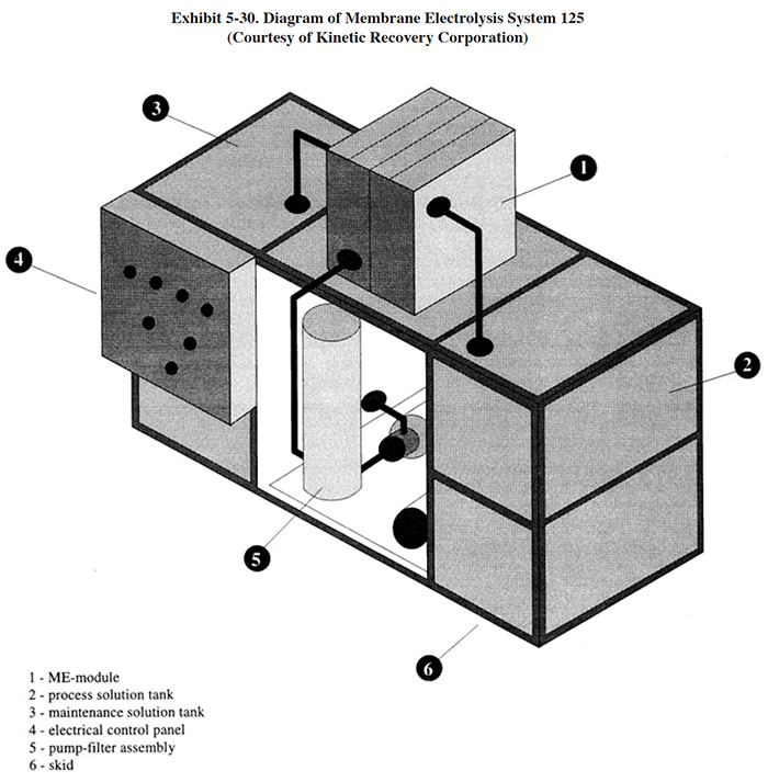
5.7.5 Costs
5.7.5.1 Capital Costs
Equipment costs for two different manufacturers of membrane electrolysis equipment are shown in Exhibit 5-31, based on their estimated removal capacity for iron from a bath containing 10 g/l of iron. Installed costs are approximately 5% to 20% higher than equipment costs.
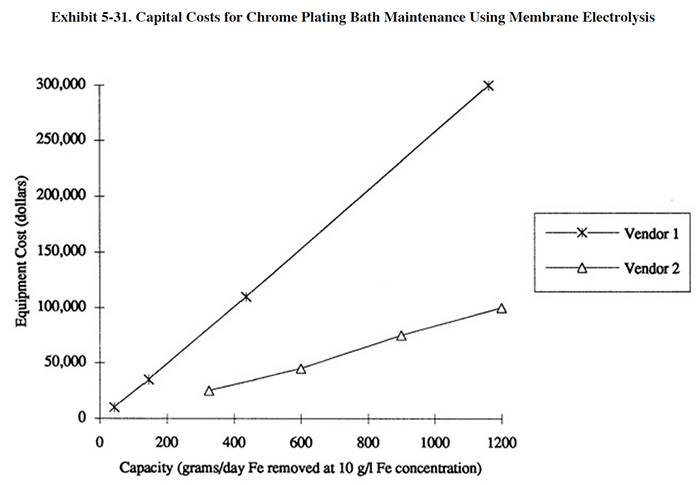
5.7.5.2 Operating Costs
Operating costs for the membrane electrolysis technology are presented in Exhibit 5-32. These are based on the operation of units designed for the removal of 400 g/day of iron from chromic acid solutions containing 4 to 10 g/l of iron.
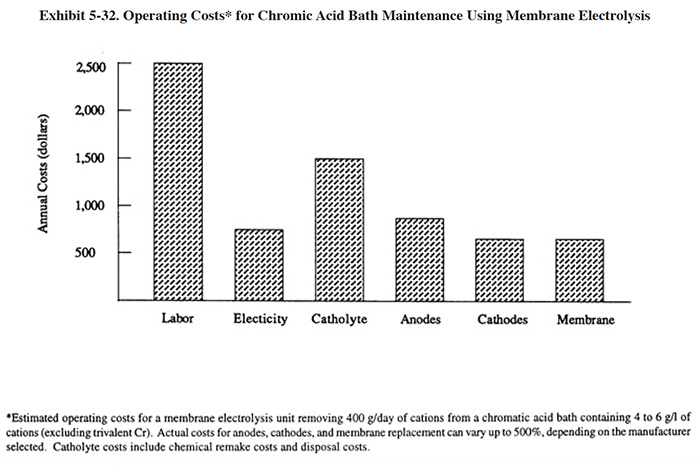
5.7.6 Performance Experience
Only five membrane electrolysis applications were identified during the Users Survey. These included two applications of in-house units built by PS 275, two applications of Ionsep units and one application of a Pentol CAPS system (manufactured in France). Detailed data were provided for all systems except for the Pentol unit. The user of that system, however, provided a short informative description of their experience. A summary of the Users Survey data are provided in Exhibit 5-33.
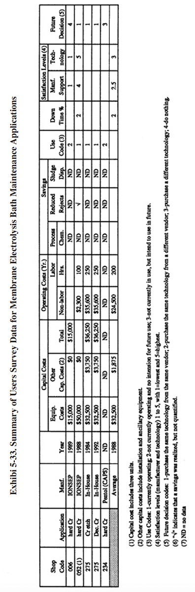
The following information and data summarize the performance experience of the survey respondents.
- Shops using membrane electrolysis for chromic acid bath maintenance gave the technology mixed ratings, even for the same manufacturer. PS 006 and PS 052, both of which purchased Ionsep units, had general satisfaction levels of 1 and 5, respectively (1= lowest and 5 = highest). The low satisfaction level from PS 006 may have been influenced or otherwise related to the manufacturer's technical support, which they also rated 1. That shop also provided the following: "Technical support info very difficult to get from vendor. Process not compatible with our bath, which we had to learn on our own." PS 052 gave a manufacturer's support rating of 4. The owner of the Pentol unit was displeased with its performance (PS 234). They wrote: Seemed limited to the removal (of) trivalent chromium... other impurities such as Cu and iron were largely unaffected."
- The following is a breakdown of the reasons why shops purchased this technology:
To meet or help meet effluent regulations: 0 To reduce plating chemical purchases: 1 To reduce the quantity of waste shipped offsite: 2 To reduce wastewater treatment costs: 0 To improve product quantity: 3 Other: 0
- The use of membrane electrolysis had a variable impact on production quality and the rate of production. The following responses were provided:
Product Quality Production Rate Improved (PS 275) 1 1 No Change (PS 052) 1 1 Decreased (PS 006) 1 1
- Although PS 052 indicated in the survey form that product quality and the production rate were not impacted, they also stated that purifying their plating solutions "reduces our reject rates which eliminates the costly need to strip the part and replate."
- None of the shops provided any estimates of savings from the operation of membrane electrolysis units.
- Membrane electrolysis may be more applicable to simple chromic acid bath chemistry (e.g., generic chromic acid/sulfuric acid hard chromium bath) more so than baths with complex chemistry (e.g., dual catalyst plating baths). This is evidenced by the difficulties of PS 006, who operated their unit on a proprietary fluoride bath (M&T CR 110), whereas PS 052, successfully operates their unit on a generic hard chromium bath.
- Two of the survey respondents have purchased and used alternative technologies for chromic acid bath maintenance. PS 006 previously used the porous pot (an ion transfer technology) and PS 234 previously used the porous pot and ion exchange. PS 006 indicated that the porous pot was "moderately successful", whereas they were unsatisfied with the membrane electrolysis unit. They indicated that both technologies caused bath chemistry problems with their proprietary plating solution. PS 234 has not been satisfied with any of the chromic acid bath maintenance technologies that they have tried and subsequently sold each of them. However, they indicated that ion exchange provided the best results of the three technologies. A complete discussion of their comments is presented in Section 5.6.8.
5.7.7 Operational and Maintenance Experience
The following summarizes the respondent's O&M experiences and provides operating labor information.
- Two shops provided operating labor data. For these shops, the average number of annual operating hours per membrane electrolysis unit were: 200 hrs/yr (assumes 250 hrs/yr for each of the two units operated by PS 275). The following is a breakdown of the responses for skill requirements (based on data from PS 006, PS 052 and PS 275):
Environmental Engineer: 0 Process/Chemical Engineer: 0 Chemist: 1 Consultant: 0 Plumber/Pipe Fitter: 0 Electrician: 0 Vendor: 0 Senior Level Plater: 1 Junior Level Plater: 0 Trained Technician: 2 Common Labor: 0 Other: 0
- Reported O&M problems for this technology include: (1) occasional clogging of pipes (PS 052); short life span of membrane and anodes (PS 006); and (3) very difficult to clean out collected residuals from unit.
- Ionsep reported the following expected life spans of system components: membrane > 12 mth, 12 to 36 mth, and cathode > 60 mth.
5.7.8 Residuals Generation
The primary residuals generated by the use of membrane electrolysis are spent catholyte and associated sludge. During the process, cations are electrically transported from the anolyte (process bath) through the ion specific membrane into the catholyte. The nature of the residual generated during the process depends mostly on the selection of the catholyte, either acid or caustic. With an acidic electrolyte (typically sulfuric acid), the electroplatable cations deposit on the cathode and the non-electroplatable cations stay in that solution as salts. Periodically, the cathode is cleaned of the sludge-type deposit and the catholyte solution is discarded and replaced (ref. 370). The smallest GOEMA unit has a catholyte volume of 10 gal (20% sulfuric acid). It is typically replaced every 4 months (30 gal/yr) (ref. 384). With a caustic catholyte (a mixture of alkalis used in a patented approach by Ionsep), the high pH converts multi-valent metal cations that enter the catholyte solution into insoluble hydroxides. The hydroxyl ions needed to react with the metal cations that enter are formed at the cathode of the cell. The precipitated metals buildup in the catholyte. With smaller systems, it is usually preferable to replace the catholyte (approximately every one to four weeks). With larger systems, the precipitated metals are separated using a filter press and the catholyte is returned to service (this practice greatly reduces the volume of waste generated by the plating/purification process). Alternatively, a conical bottom catholyte tank can be employed and the solids (with some catholyte) can be drained from the cone of the tank and disposed of as a slurry. In some cases, the metal hydroxides are reusable for other purposes (e.g., ferrous hydroxide, which can be used for making pigments, is produced during applications with steel pickling solutions). The Ionsep catholyte tank typically has a volume of 55 gal (plastic drum), although large installations may have tanks with volumes up to 300 gal.
Two shops operating the Ionsep system provided data on residuals production. PS 006 operated the process on a 2,800 gal hard chromium bath (3 plating tanks). They generated 55 gal/wk (2,860 gal/yr) of spent catholyte. PS 052 operated the process with 12,700 gal of hard chromium solution (7 plating tanks) and generated 55 gal/month (660 gal/yr) of spent catholyte.
If a plating shop using membrane electrolysis has a conventional wastewater treatment system in place, the spent
catholyte could be bled to this system or batch treated and then discharged to the general treatment system.
Treatment of the catholyte will generate a sludge that under most conditions will be considered a RCRA F006 sludge.
The sludge volume will depend mainly on the metal content of the catholyte and the dryness (percent solids) of the
resultant sludge.
Spent catholyte may meet the characteristics of a hazardous waste due to its pH and or toxic metals content
(particularly chromium). Treatment of the catholyte may be interpreted as a hazardous waste treatment process (RCRA
controlled) rather than wastewater treatment (Clean Water Act controlled), especially for shops that have achieved
zero discharge. Before developing a treatment and disposal scheme, the plater must investigate applicable RCRA and
Clean Water Act rules, including state and local regulations, relative to the treatment process.
5.8 DIFFUSION DIALYSIS
5.8.1 Overview
Diffusion dialysis is an ion exchange membrane technology that competes with acid sorption (Section 5.5) as a purification/recovery method for acids that have become contaminated with metals (e.g., pickling, anodizing, stripping, etching, and passivation baths).
The diffusion dialysis process separates acid from its metal contaminants via an acid concentration gradient between two solution compartments (contaminated acid and deionized water) that are divided by an anion exchange membrane. Acid is diffused across the membrane into the DI water whereas metals are blocked due to their charge and the selectivity of the membrane. A key difference between diffusion dialysis and other membrane technologies such as electrodialysis or reverse osmosis is that diffusion dialysis does not employ an electrical potential or pressure across the membrane. Rather, the transport of acid is caused by the difference in acid concentration on either side of the membrane. As such, the energy requirements for this technology are low.
Exhibit 5-34 describes the diffusion dialysis process. The process uses ion exchange membranes which are assembled in a membrane stack. The membrane separates two liquids: (1) acid contaminated with metal and (2) deionized water. The physical laws of diffusion and electroneutrality cause material in high concentration to move to an area of low concentration without an imbalance of electrical charge. Because of the presence of the anion membrane, the metals in the concentrated solution are unable to pass from the concentrate to the DI water. However, anions in the concentrate (e.g., chlorides, sulfates, nitrates, phosphates) are permitted passage. Also, hydrogen ions, although positively charged, diffuse along with the disassociated acid (anions). The passage of hydrogen, which is key to the success of this process, is due to the small size of the hydrogen molecules and their mobility. The passage of the positively charged hydrogen ions satisfies the law of electroneutrality, preventing an imbalance of ionic charge on either side of the membrane (ref. 192, 336).
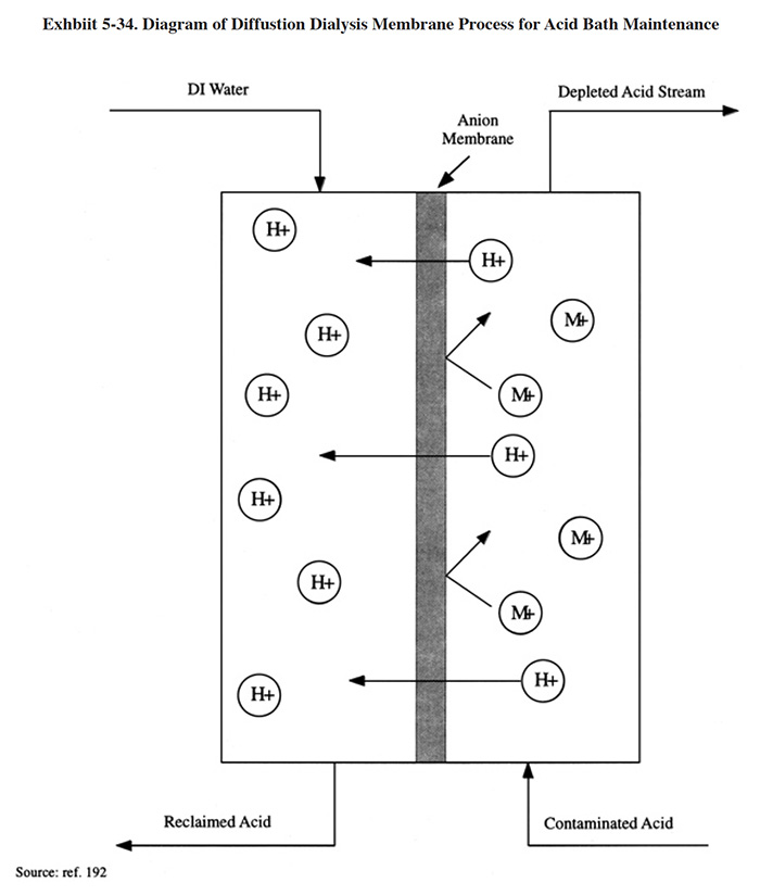
Diffusion dialysis, like other membrane technologies, is not 100 percent efficient; not all of the acid will be recovered and some leakage of metal will occur. In the laboratory, the process has yielded acid recovery efficiencies as high as 99% with 98% metal removal. In the manufacturing environment, the practical limits are 80% to 95% acid recovery with 60% to 90% of the metal contaminants removed. Also, the recovered acid may be of insufficient concentration to permit direct reuse. In such cases, vacuum evaporation may be needed to increase its concentration (ref. 338), although the economics of a concentration step are questionable. One source indicates, based on 1.5 years of experience with diffusion dialysis, that it is more efficient and economical than acid sorption for certain applications (e.g., recovery of mixed acid pickling baths) (ref. 336).
A related predecessor to this technology, Donnan dialysis, was a popular research topic for the metal finishing industry in the late 1970's (ref. 39). Donnan dialysis is more often associated with metal recovery applications (e.g., nickel and copper) using cation membranes than with acid bath maintenance. However, anion membrane applications of Donnan dialysis, including metal recovery from cyanide solutions are also discussed in the literature (ref. 39, 380). The recovery of nickel from rinse water was one of the primary targets of this technology. This was accomplished by separating nickel bearing rinse water from a low pH solution using a cation membrane. Nickel ions from the rinse water would replace hydrogen ions in the cation membrane matrix and pass from the nickel rinse water to the low pH solution while the hydrogen ions passed into the rinse water. Simultaneously, hydrogen ions must be replaced in the low pH solution from an outside source to maintain electroneutrality and the driving force for ion transfer. To maintain electroneutrality, two hydrogen ions (2H+) must move from the low pH solution to the rinse water when one nickel ion (Ni++) is transferred. Anions present in either compartment are restricted from migration due to the use of the cation membrane (ref. 39). No commercial metal finishing applications of Donnan dialysis are known to exist.
5.8.2 Development and Commercialization
The development of diffusion dialysis as a practical recovery technology took place in the early 1980's in Japan. In 1984 a device for the recovery of nitric and hydrofluoric acids from a mixed acid waste was installed at the Kashima works of Nippon Stainless Steel Co. (ref. Graver file.) The first European commercial application of diffusion dialysis identified in the literature took place in Sweden in 1989. That system, which is applied to the regeneration of a stainless steel pickling acid (HF/HNO3), was still in operation in 1993. Only one U.S. application of the technology was identified during the project (caustic recovery from an aluminum etch bath at Caspian, Inc., San Diego, 1992). That system processes the etch solution from three milling tanks with a total solution volume of 72,000 gal. Three U.S. vendors of this technology were identified during the Vendors Survey (Kinetic Recovery Corporation, Baker Brothers and Graver Water Division of the Graver Company).
5.8.3 Applications and Restrictions
The diffusion dialysis process has been applied for the purification of hydrochloric, nitric, hydrofluoric,
phosphoric, and sulfuric acids, including mixed acids; and ferric chloride etchant (ref. 192, 252, 336)
The most common applications of this technology include:
- Recovery of mixed acids of stainless steel pickling baths (ref. 336).
- Recovery of H2SO4/HCl or H2SO4/HNO3 of pickling plants
for non-ferrous metals such as zinc and aluminum (ref. 336).
- Recovery of H2SO4 and HCl of steel and non-ferrous metal pickling baths (ref. 336).
- HCl and HNO3 acid rack strips (ref. 192).
- H2SO4 anodizing solutions (ref. 192).
- Regeneration of battery acids (ref. 252).
Like acid sorption, diffusion dialysis is limited in applicability by the strength of acid that it can produce. If highly concentrated acids are processed, the resultant product will not be of sufficient strength for direct reuse and the addition of concentrated acid is not practical because it increases the total volume of the solution beyond the capacity of its tank. A vacuum evaporator could be employed to concentrate the acid to bath strength; however, this would most likely make the overall recovery process uneconomical. Examples of successful applications in the literature are shown in Exhibit 5-35, where the original acid concentrations are in the range of 3.4 to 4.7 N.
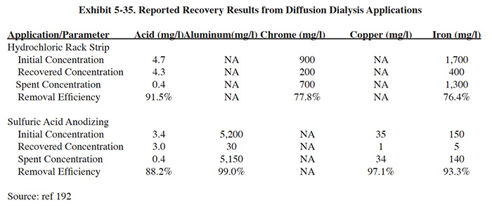
The diffusion dialysis membrane material is relatively resistant to chemicals commonly used in the plating shop. However, contact with solvents could cause swelling of the membrane and strong oxidizing agents such as chromic acid can deteriorate the membrane material (ref. 252). The process is tolerant of feed solution temperatures up to 50°C (ref. 252).
A process diagram for diffusion dialysis is shown in Exhibit 5-36. Acid is pumped through one side of an ion exchange membrane stack and water flows through the other side of the membrane in the opposite direction. Prefiltering of the acid is needed to prevent fouling of the membrane. Most of the acid diffuses through the membrane and into the clean water producing a clean acid stream. The metal and a percentage of the acid remains in the original acid stream, which is directed to treatment. The acid product is monitored for strength and adjusted with concentrated acid as necessary.

5.8.4 Technology/Equipment Description
5.8.4.1 General
Diffusion dialysis equipment resembles that of other membrane technologies such as electrodialysis. These units are designed with a stacked membrane configuration. A "membrane stack" consists of a number of thin membrane compartments created by alternating layers of ion-specific membranes and spacers. The spacers are present to permit solutions (i.e., contaminated acid and DI water) to flow between the membrane layers. The membranes and flow spacers are held together by a cell frame and clamping unit, giving the membrane stack the appearance of a plate and frame filter press (ref. 252, Kinetic Recovery Corporation file).
The commercial diffusion dialysis units usually employ co-polymer membranes of polystyrene and divinylben-zene. These units permit the diffusion of highly disassociated acids through the polymer structure while cations (metals) remain behind because of their positive electrical charge. The mass transfer through the membrane was described by Reinhard (ref. 252) as:
jn = K x A x Cn
where, jn is the overall transport rate of solute n,
Cn is the average solute concentration difference between the fluids,
A is the membrane area, and
K is the overall rate constant (dialysis coefficient).
The proper average solute (acid) concentration difference is the logarithmic mean of the inlet and outlet differences. The dialysis coefficient is a function of: (1) chemical characteristics of the acid; (2) concentration of the acid; (3) chemical characteristics of the salt; and (4) temperature of liquid (ref. 252).
The temperature of the feed appears to be a significant variable. One vendor indicates that a temperature drop of 3.6 °F (2.0° C) will reduce the recycling rate by approximately 1.5%. The membranes can typically withstand temperatures up to 122°F (50°C). They also indicate that heating of the feed stream may be required for winter operation (ref. Kinetic Recovery Corporation file).
The diffusion dialysis technology is commercially available in a wide range of capacities. Existing systems were identified with inlet acid flows ranging from 100 gpd to 2,000 gpd (ref. 192, 336).
5.8.4.1 Commercial Equipment
This subsection contains a description of commercially available diffusion dialysis equipment that is manufactured and/or sold by Vendor Survey respondents. This is intended to provide the reader with information and data on a cross section of available equipment. Mention of trade names or commercial products is not intended to constitute endorsement for use.
Kinetic Recovery Corporation markets a series of diffusion dialysis units that have been used in Germany and Sweden for more than two years on the following applications: HNO3/HF (stainless steel); H2SO4/HCl (zinc or aluminum); H2SO4/HNO3 (zinc or aluminum); H2SO4 (iron or zinc); and HCl (iron or zinc). They have also tested a unit at United Technologies on a HNO3/HF (titanium). Each of their systems are custom made and include: tanks for acid and DI water; level controls; membrane stack, internal plumbing and connections to tanks; automatic valves; feed pump; cartridge filter; and control panel. The units are skid mounted and factory assembled. The normal range of capacities is from 30 to 415 gpd of acid feed.
5.8.5 Costs
5.8.5.1 Capital Costs
Diffusion dialysis units can be operated on either a batch or continuous basis. When operated on a batch basis the units are sized to process the contaminated acid bath within a period permissible downtime period. More frequently, the units are operated on a continuous basis and are sized based on the contaminant introduction rate. In this case, the minimum sized system is one that is capable of processing the entire bath volume in the same time interval that dumping had been previously scheduled (ref. 192). Owing to the newness of the technology, it may be prudent for the user to validate design expectations through pilot testing (ref. 192).
Capital costs for diffusion dialysis equipment is shown in Exhibit 5-37.
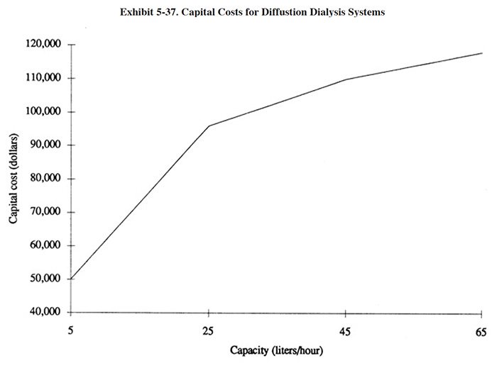
5.8.5.2 Operating Costs
The primary operating cost items for the diffusion dialysis technology include: O&M labor, energy, DI water, and membrane replacement. The operating costs were estimated by a vendor to be $0.78 per gallon of acid feed (ref. Kinetic Recovery Corporation file).
5.8.6 Performance Experience and Operational and Maintenance Problems
As indicated previously, none of the respondents to the Users Survey indicated that they have employed this technology and therefore no firsthand performance experience is available. Various literature sources have reported on the efficiency of the diffusion dialysis process (ref. 192, 252, 336). These articles and conference papers, written by equipment manufacturers and suppliers, indicate that 80 to 95 percent of the initial acid can be recovered with 60 to 95 percent of the contaminant metal removed (i.e., a residual metal content of 5 to 40 percent of original concentration remains in the recovered acid).
Vendors of the technology suggest that the extremely low pressure feed of diffusion dialysis puts minimal stress on the stack components and therefore, increases the longevity of the units. However, as with any membrane technology, there is concern over membrane fouling and deterioration. Membrane fouling is most frequently caused by the presence of solids in the acid feed solution. It is reported (ref. 252, 336) that prefiltering will effectively eliminate the potential fouling problem. With prefiltering, membrane cleaning is required approximately two times per year (ref. 252).
Organic substances (e.g., oil and grease) can also cause membrane fouling. This problem can be overcome using a pretreatment of the raw acid solution with activated carbon.
Membrane life is reported to be three to seven years (ref. 252, 336). Membrane life will be shortened when the technology is used with hydrogen peroxide, chromic acid, and nitric acid with concentrations over 20 percent, as well as temperatures over 45°C and organic substances such as oil and grease, solvents or cleaners (ref. 336).
5.8.7 Residuals Generation
Use of the diffusion dialysis technology will generate a depleted acid stream that is equal in volume to the original contaminated acid bath and contains approximately 5 to 20% of the original acid content and 5 to 40% of the original metal content.